Antenna tuning system and method thereof
a tuning system and antenna technology, applied in antennas, transmission monitoring, electrical equipment, etc., can solve the problems of multi-path fading and interference caused by omni-antenna, and achieve the effect of avoiding energy was
- Summary
- Abstract
- Description
- Claims
- Application Information
AI Technical Summary
Benefits of technology
Problems solved by technology
Method used
Image
Examples
first embodiment
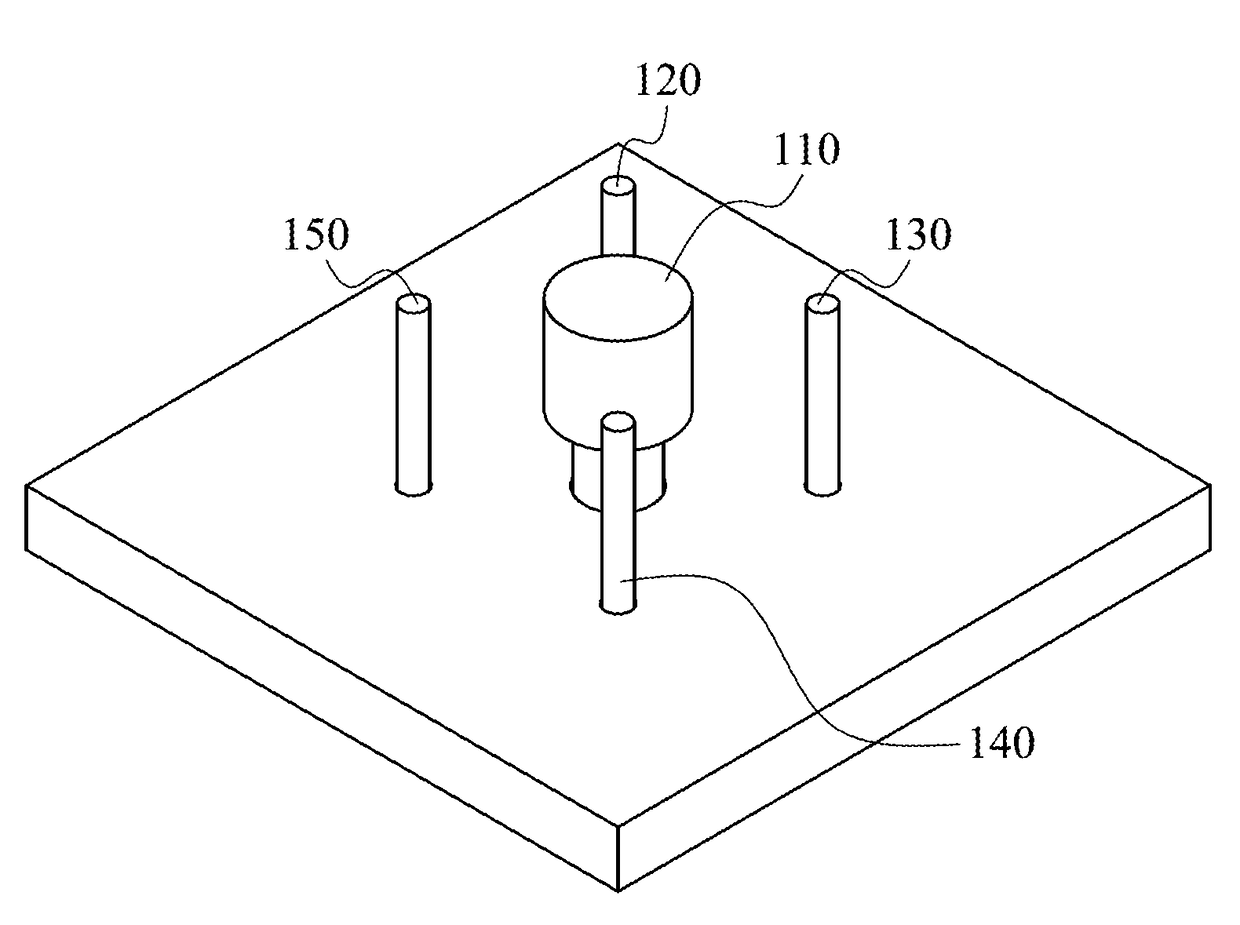
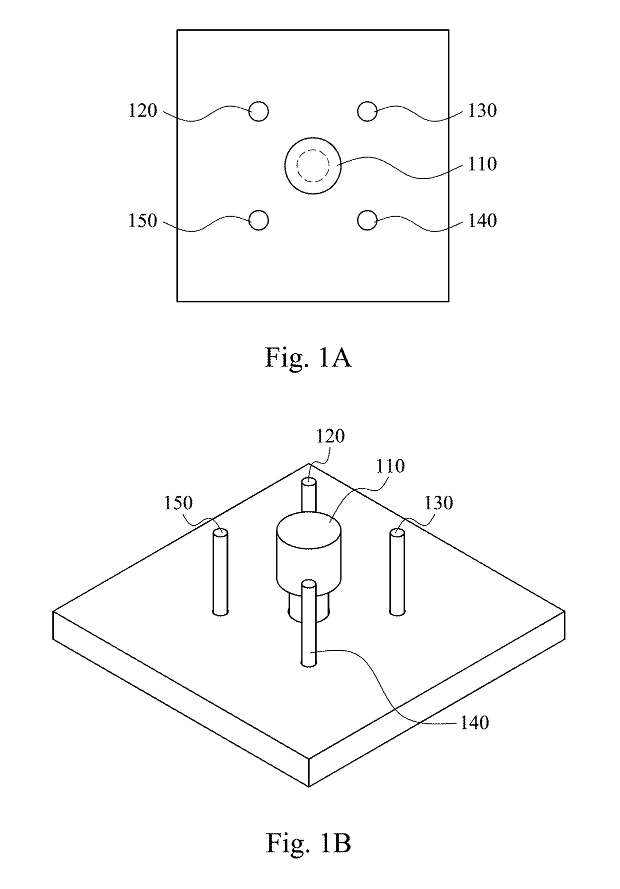
[0025]FIG. 1A and FIG. 1B are block diagrams for configurations of main antenna and a plurality of parasitic antennae of the antenna tuning system according to the present invention. In FIG. 1A and FIG. 1B, four parasitic antennae 120, 130, 140, and 150 surround the main antenna 110. The main antenna 110 and the parasitic antennae 120, 130, 140, and 150 of the present invention are monopole antennae in the present embodiment. The distance between the main antenna 110 and the parasitic antennae 120, 130, 140, and 150 is quarter of the operating wavelength in the present embodiment. However, the actual planning is not limited thereto. The antenna tuning system of the present invention can determine that the radiation energy of the target station generated by different parasitic antennae combing with the main antenna 110. The antenna tuning system also chooses the related parasitic antenna having the greatest resonance effect so as to let the target station have the greatest communicat...
second embodiment
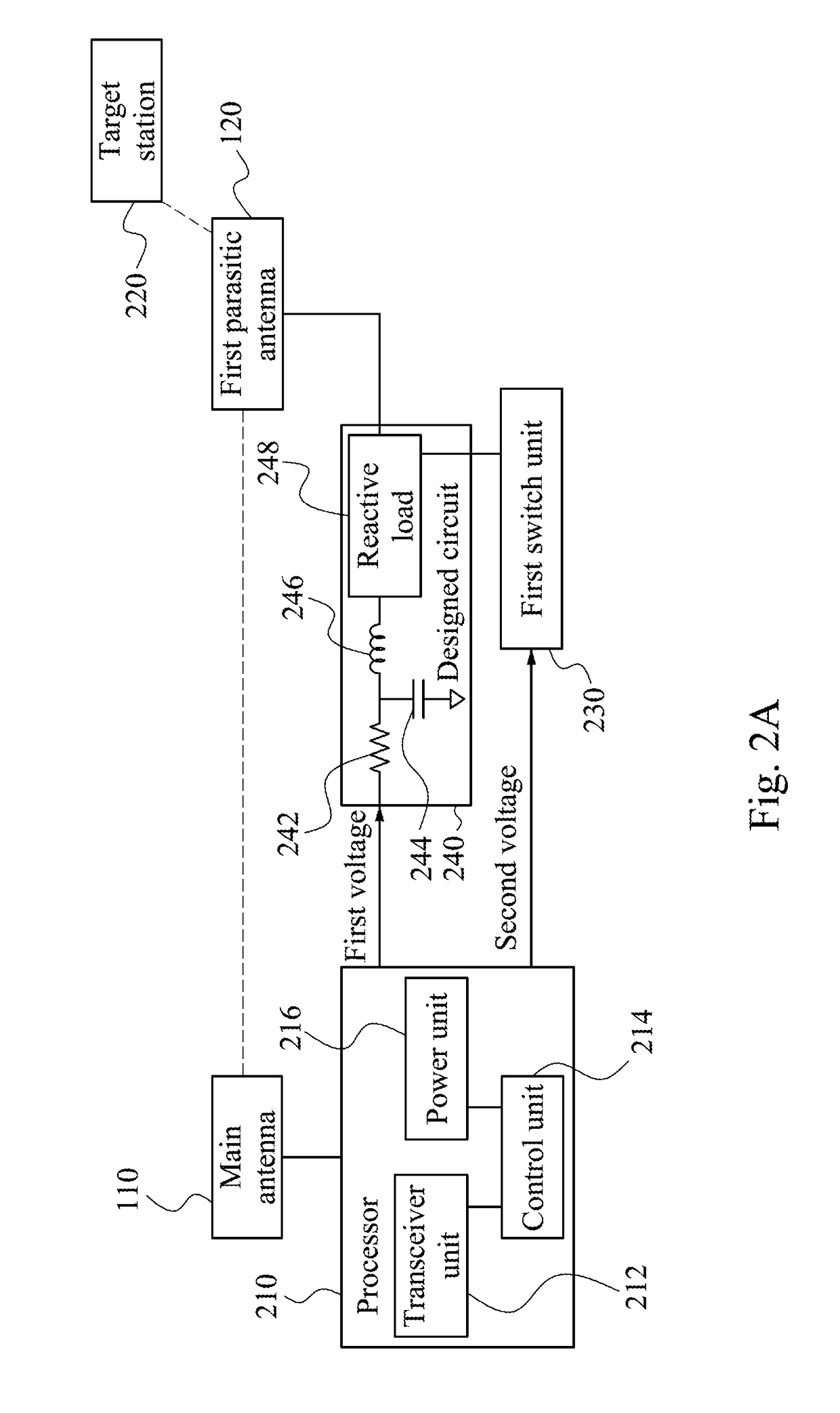
[0034]In the second embodiment, the control unit 214 can choose the first switch unit 230 or the second switch unit 235 of the two switch units and turns on it. Accordingly, the antenna tuning system of the present invention can have the inductive load 258 and the capacitive load 268 selectively. It is worth noting that capacitive components, for example, DC block condensers 270 and 276, are installed at the connected point between the first parasitic antenna 120, the inductive load 258, and the capacitive load 268 to separates different DC control signal from the first switch unit 230 and the second switch unit 235 respectively in order to prevent the two switch units from interfering each other. Therefore, the processor 210 controls the first switch unit 230 through the first voltage and the second voltage and controls the second switch unit 235 through the third voltage and the fourth voltage in order to implement choosing or switching different property of reactive loads. For ex...
PUM
 Abstract
Description
Claims
Application Information
 - R&D
- Intellectual Property
- Life Sciences
- Materials
- Tech Scout
- Unparalleled Data Quality
- Higher Quality Content
- 60% Fewer Hallucinations
Browse by: Latest US Patents, China's latest patents, Technical Efficacy Thesaurus, Application Domain, Technology Topic, Popular Technical Reports.
© 2025 PatSnap. All rights reserved.Legal|Privacy policy|Modern Slavery Act Transparency Statement|Sitemap|About US| Contact US: help@patsnap.com


