
Paddle wheel for paddle wheel ship

A technology of paddle steamers and paddle wheels, applied in the field of paddle steamers, can solve the problems of wasting kinetic energy, wasting a small amount of kinetic energy, and a large proportion of useless work, and achieve the effects of improving propulsion efficiency, avoiding energy waste, and reducing useless work

Inactive Publication Date: 2010-07-07
侯宇涵
View PDF4 Cites 11 Cited by
  • Summary
  • Abstract
  • Description
  • Claims
  • Application Information

AI Technical Summary

Problems solved by technology

When the paddle wheel rotates at a low speed, the water-entry stroke of the paddle is in the state of pumping water downward, and the water-out stroke of the paddle is in the state of upward water pumping. The proportion of useless work in both states is relatively large, thus wasting a lot of kinetic energy; therefore, the paddle wheel at low speed Very inefficient propulsion while spinning
When the paddle wheel rotates at a high speed, the water entry stroke of the paddle blade is in the state of slapping the water downward, and most of the water body being slapped flies downward, and the paddle wheel obtains an upward reaction force, which is used to support the gravity of the hull, which is useful work; Slapping a small part of the water body flies upwards, which is useless work, thus wasting a small amount of kinetic energy; when the paddle leaves the water, the state is idling, because the water body in front of the paddle has been emptied; therefore, although the paddle wheel rotates at high speed The propulsion efficiency of the propulsion efficiency is higher than that of low-speed rotation, but it is still not ideal

Method used


Image

  • Paddle wheel for paddle wheel ship
  • Paddle wheel for paddle wheel ship
  • Paddle wheel for paddle wheel ship

Examples


Embodiment Construction

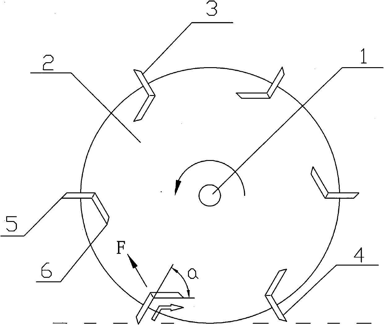
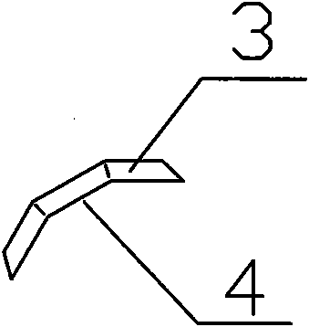
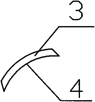
[0015] Such as figure 1 As shown, the paddle wheel used for paddle steamers according to the present invention consists of a wheel shaft 1, a wheel hub 2 installed around the wheel shaft 1, and six blades 3 arranged radially and evenly on the outer edge of the wheel hub 2. The water-repelling surface 4 of the paddle 3 is composed of two interconnected planes, the water-repelling surface 4 of the paddle 3 is deflected from the outer edge 5 to the inner edge 6 to the direction of rotation of the paddle wheel, and the deflection angle a is 60° degree; the outer edge 5 of the water-repelling surface 4 and the end surface of the paddle 3, and the inner edge 6 and the end surface of the paddle 3 are all acute angles. Such as figure 2 As shown, the water repelling surface 4 of the paddle 3 may also be composed of three planes. Such as image 3 As shown, the water-repelling surface 4 of the paddle 3 can also be an arc surface. Such as Figure 4 As shown, the water-repelling surf...


PUM


Abstract

The invention discloses a paddle wheel for a paddle wheel ship, which comprises a wheel shaft, a wheel hub arranged around the wheel shaft, and paddles which are uniformly arranged on the outer edge of the wheel hub, wherein the water-repelling surface of the paddle is formed by at least two flat surfaces or camber surfaces which are connected with each other or by a flat surface and a camber surface which are connected with each other; and the water-repelling surface of the paddle deflects to the rotating direction of the paddle wheel from the outer edge to the inter edge, with the defection angle Alpha larger than 10 degrees and less than 120 degrees. The invention has the advantages that the energy waste during the high-speed rotation of the paddle wheel is avoided, the water-repelling surface of the paddle deflects to the rotating direction of the paddle wheel from the outer edge to the inter edge by 10 degrees to 120 degrees, so when the paddle repels water, the movement direction of water body flying off upward can be changed, and an extra upward counter acting force can be obtained, so the useful work is increased, and the idle work can be reduced, thus realizing the improvement of propulsive efficiency of the paddle wheel when in high-speed rotation.

Description

technical field [0001] This invention relates to paddle steamers, and more particularly to paddle wheels for paddle steamers. Background technique [0002] The paddle wheels used in traditional paddle steamers have flat plate blades. When the paddle wheel rotates at a low speed, the water-entry stroke of the paddle is in the state of pumping water downward, and the water-out stroke of the paddle is in the state of upward water pumping. The proportion of useless work in both states is relatively large, thus wasting a lot of kinetic energy; therefore, the paddle wheel at low speed The propulsion efficiency while rotating is very low. When the paddle wheel rotates at a high speed, the water entry stroke of the paddle blade is in the state of slapping the water downward, and most of the water body being slapped flies downward, and the paddle wheel obtains an upward reaction force, which is used to support the gravity of the hull, which is useful work; Slapping a small part of ...

Claims


Application Information

Patent Timeline
IPC IPC(8): B63H1/04
Inventor 侯宇涵侯亮贾凤琴
Owner 侯宇涵
Learn More