
Electric immersion heater for diesel exhaust fluid reservoir

a technology of fluid reservoir and electric heater, which is applied in the direction of ohmic-resistance heating, mechanical equipment, machines/engines, etc., can solve the problems of slow system activation, increased cost and complexity of the system, and achieve faster, more efficient heating or thawing

Active Publication Date: 2018-06-21
THE GATES CORP
View PDF8 Cites 3 Cited by
  • Summary
  • Abstract
  • Description
  • Claims
  • Application Information

AI Technical Summary

Benefits of technology

The invention relates to a method for quickly and efficiently heating or thawing fluid in a system using a thermoplastic encapsulation material that can be extruded and thermoformed onto a heating element. This method may result in faster heating than previous methods and may eliminate the need for heated engine coolant in conventional SCR systems. The temperature of the system can be controlled through the use of semi-conductive fiber or filament and voltage. The invention may provide a more cost-effective solution for heating fluids in various configurations.

Problems solved by technology

Thawing occurs at a much slower rate in a tank than in a transfer line, because of the greater fluid volume, leading to slow activation of the system.
The time required to thaw the DEF is determined in part by the time for the engine coolant to warm up after the engine is started, and that is typically the rate-limiting step delaying the startup up of the emissions control system.
In addition to lack of temperature control of the coolant, the cost and complexity of the system is increased by the need for coolant lines running to and from the DEF tank.

Method used


Image

  • Electric immersion heater for diesel exhaust fluid reservoir
  • Electric immersion heater for diesel exhaust fluid reservoir
  • Electric immersion heater for diesel exhaust fluid reservoir

Examples


Embodiment Construction

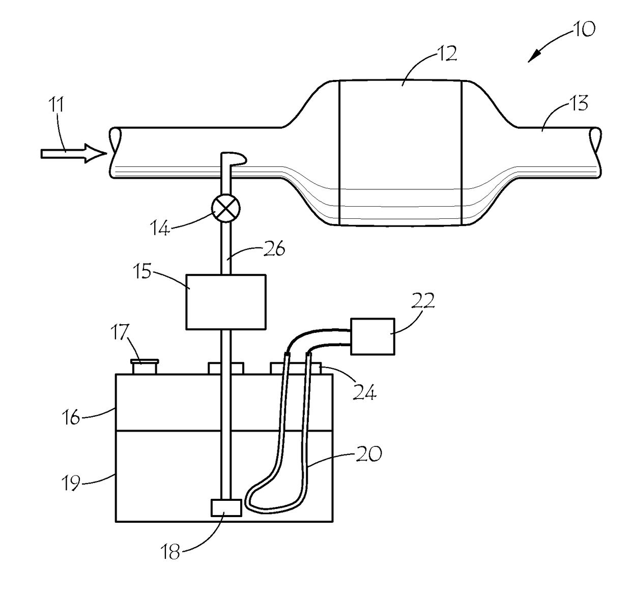
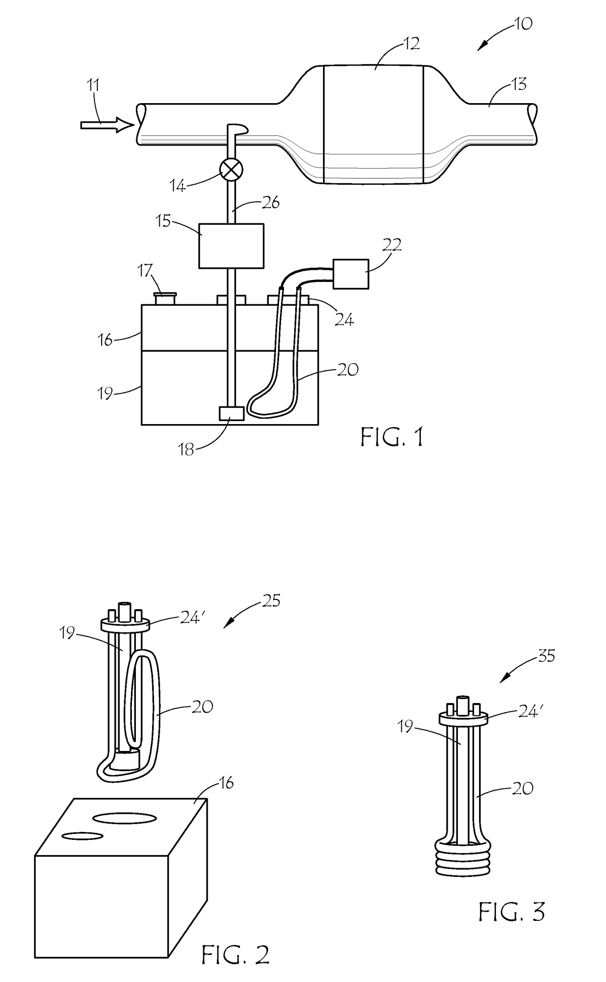
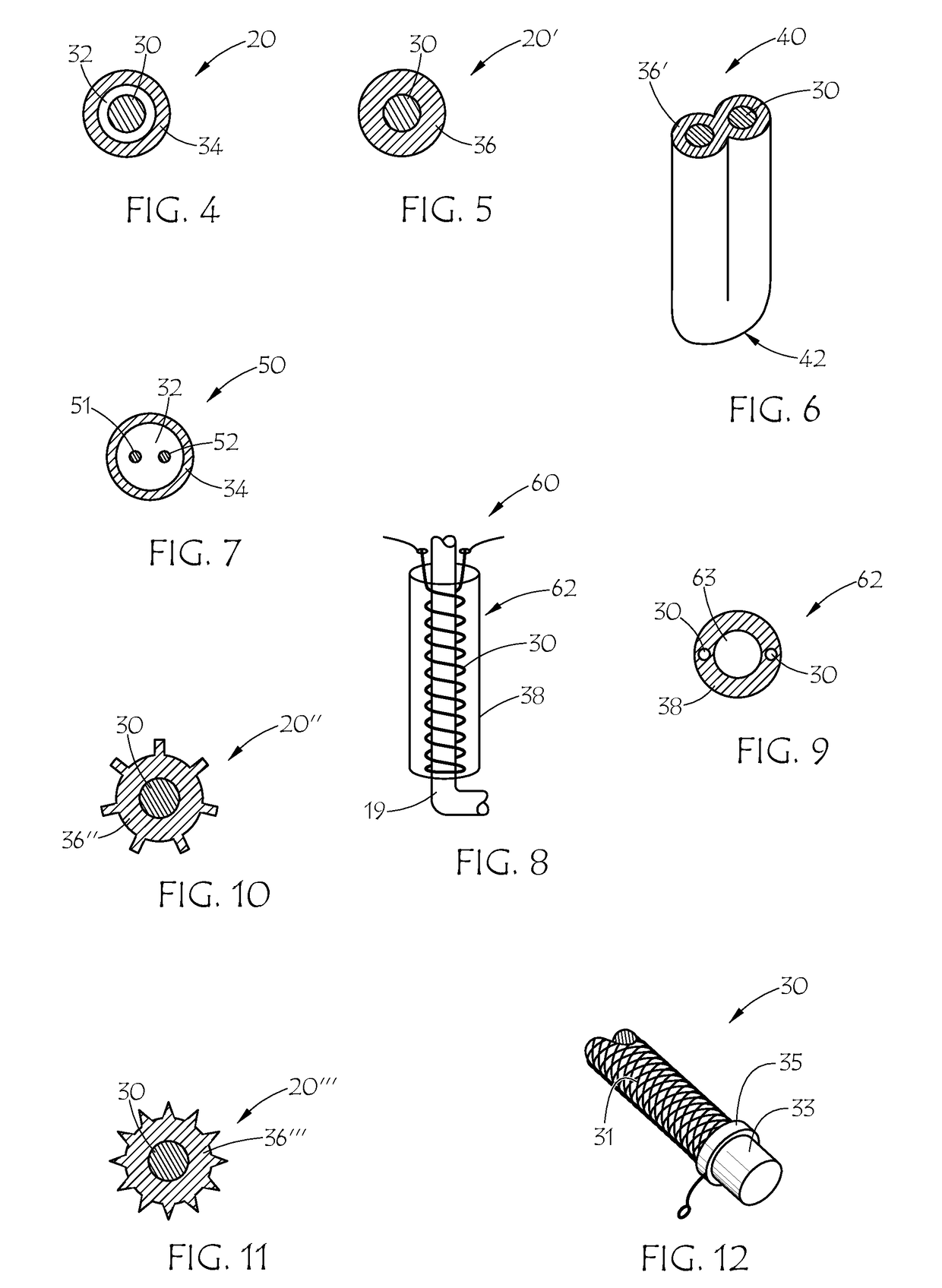
[0023]The present invention is directed to immersion heaters, systems and methods which can be used to heat a fluid in a reservoir or storage tank. The immersion heater is an electrically heated line that may warm the fluid in a tank in which it is immersed, prevent freezing of the fluid, or melt frozen fluid. Embodiments of the immersion heater may use a semi-conductive, resistive heating element housed or encapsulated within a tube or other extruded shape of electrically insulating material. The immersion heater has application, for example, in DEF tanks used in SCR systems for diesel engines.

[0024]The immersion heater may utilize an encapsulated carbon fiber, carbon fiber yarn, resistive heating wire, or other resistive heating element. The heater can be immersed in fluid (or frozen fluid) to efficiently heat a fluid or thaw a frozen fluid. The temperature of the system can be closely controlled by the amount and type of carbon fiber or other resistive heating element used, and m...


PUM

PropertyMeasurementUnit
Shapeaaaaaaaaaa
Electrical conductoraaaaaaaaaa
aaaaaaaaaa

Abstract

An immersion heater including an encapsulated, semi-conductive, heating element. The heating element may be a non-metallic, carbon-based material in the form of a monofilament, a yarn or bundle of semi-conductive fibers which may be twisted, braided fibers or yarns, or the like. The encapsulation may be in the form of a tube of one or more layers of encapsulation material(s) with the heating element inserted therein. Alternately, the heating element may be thermoplastic with semi-conductive carbon additive, and the heating element may be coated with one or more external layers of insulating encapsulation material(s). The encapsulation material may be a rubber or thermoplastic material with sufficient chemical resistance to be immersed in a reservoir of fluid subject to freezing or thickening at low temperatures, such as DEF. The heater may be thermoformed into a predetermined fixed shape.

Description

BACKGROUND OF THE INVENTION[0001]This invention relates generally to electric immersion heaters for fluid reservoirs, and more particularly to an immersion heater with carbon-based, semi-conductive heating element encapsulated in a thermoplastic sheath and diesel exhaust fluid storage systems incorporating the immersion heater.[0002]Selective Catalytic Reduction (“SCR”) is increasingly used in diesel driven vehicles to meet emissions standards, such as the Euro V or Euro VI standards for road-driven vehicles in Europe, or the EPA Tier IV standards for off-road diesel engines of all sizes used in a wide range of construction, agricultural and industrial equipment in the US. Typically, the SCR vehicle has a urea tank, separate from the fuel tank, which is used to carry an operating fluid such as an automotive urea solution (“AUS”) or diesel exhaust fluid (“DEF”), (hereinafter both or either will be referred to as “DEF”). DEF is a 32.5% solution of high purity urea in de-mineralized wa...

Claims


Application Information

Patent Timeline
IPC IPC(8): F01N3/20H05B3/14H05B3/18F01N3/28
CPCF01N3/2066H05B3/145F01N3/2896F01N3/206H05B3/18F01N2240/16F01N2530/02F01N2530/18F01N2530/22F01N2610/02F01N2610/10F01N2610/107F01N2610/1406F01N2610/1486H05B3/58H05B2214/02Y02A50/20Y02T10/12H05B3/00
Inventor SAUPE, TIMHOLT, BRIAN
Owner THE GATES CORP
Learn More