
Swivel arrangement for a carousel filler

a carousel and filler technology, which is applied in the direction of liquid bottling, packaging goods, special packaging, etc., can solve the problems of high manufacturing cost, large amount of load, and components such as bearings and bushings taking up a large amount of load, and achieve the effect of improving the current state of the ar

Inactive Publication Date: 2018-06-21
TETRA LAVAL HLDG & FINANCE SA
View PDF0 Cites 2 Cited by
  • Summary
  • Abstract
  • Description
  • Claims
  • Application Information

AI Technical Summary

Benefits of technology

The present invention is about a swivel arrangement for a carousel filler with a rotating tank and a product pipe that allows the relative speed between tank connecting part and pipe connecting part to be reduced. This reduces wear and tear on components in the swivel arrangement, increasing its lifetime and allowing for higher rotational speeds. The swivel arrangement includes a tank connecting part, an intermediate part, and a pipe connecting part. The intermediate part rotates with a different speed than the tank connecting part, reducing the relative speed and wear and tear on the components. The swivel arrangement also includes first and second bushings and first and second sets of seals to prevent contaminations and wear and tear. Overall, the invention reduces maintenance costs and increases efficiency of the carousel filler.

Problems solved by technology

Hence, there are many features included and consideration made while designing the swivel arrangement due to the requirements on the sterile environment for the tank or product which inherently consume much energy such as heated steam or make the swivel arrangement complex and thus expensive to manufacture.
Further, due to the above consideration for keeping a sterile environment, the rotational speed of the rotating tank and thus carousel filler is limited, as components such as bearings and bushings taking up large amount of the load would otherwise fail with an unacceptable frequency.

Method used


Image

  • Swivel arrangement for a carousel filler
  • Swivel arrangement for a carousel filler
  • Swivel arrangement for a carousel filler

Examples


Embodiment Construction

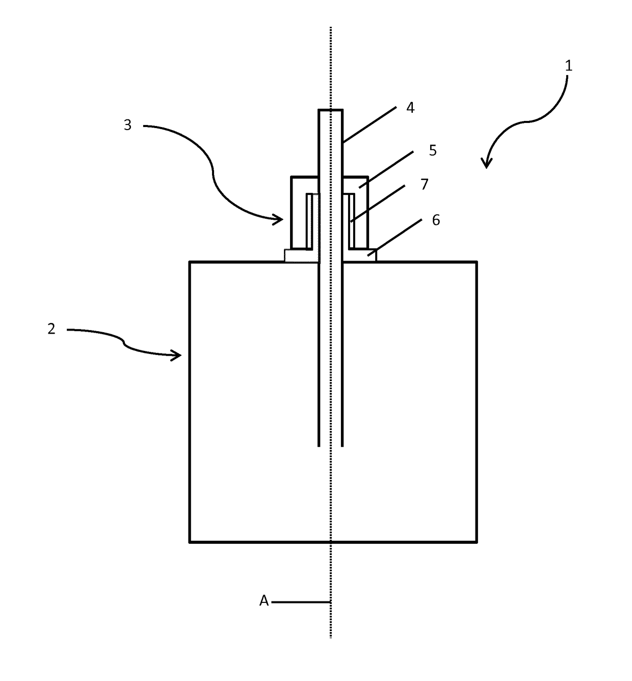
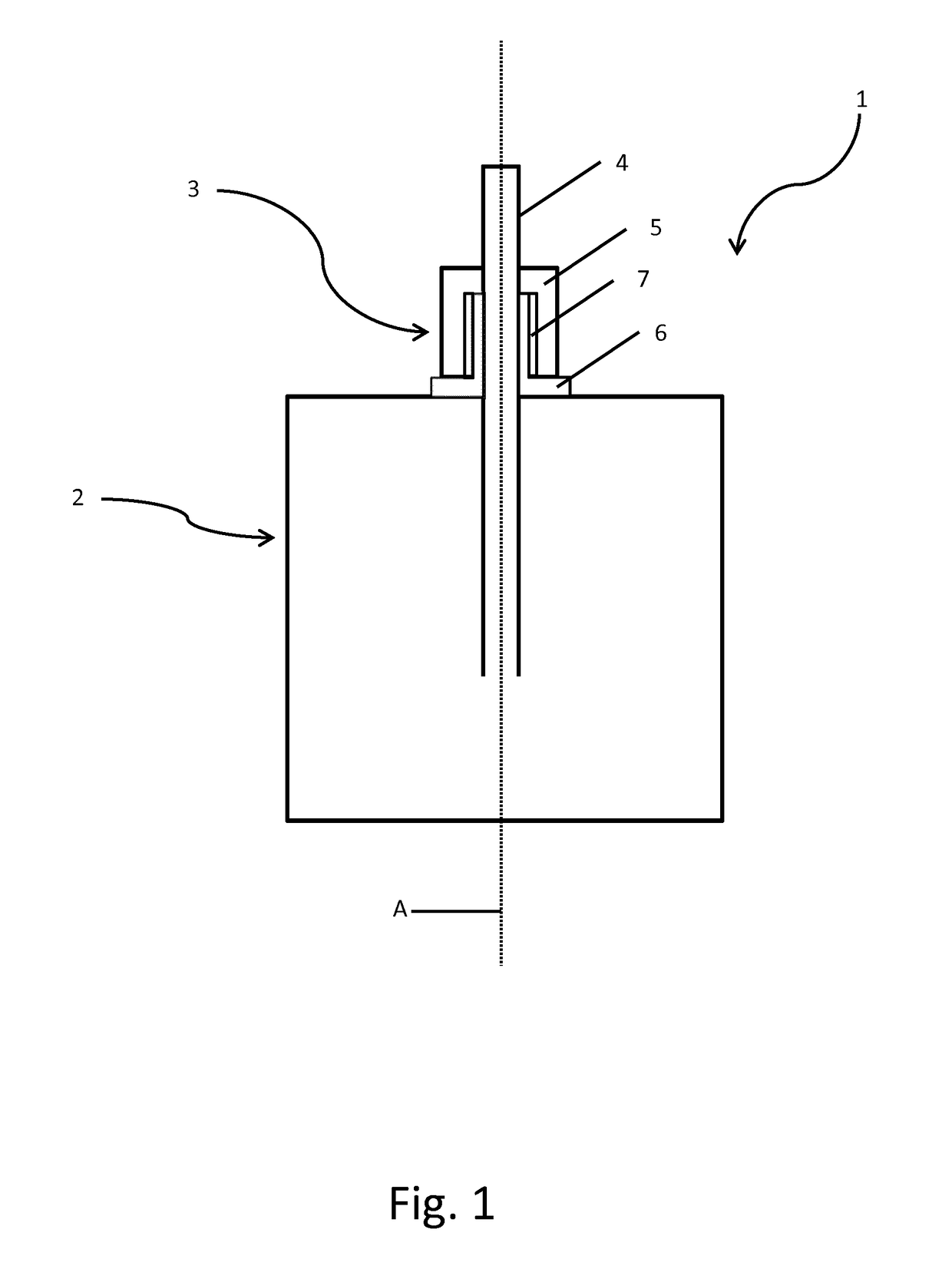
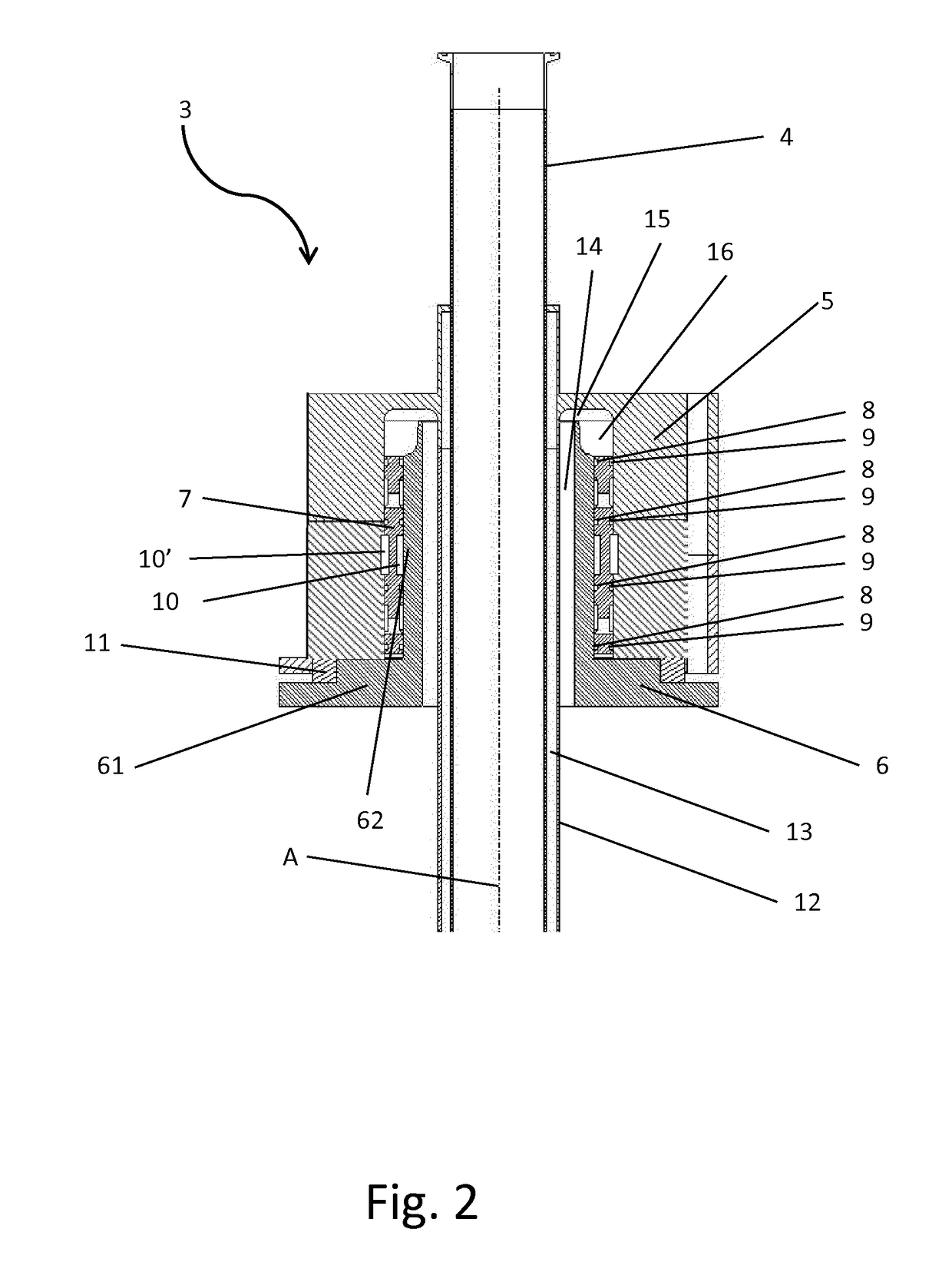
[0027]In the present detailed description, embodiments of a carousel filler and swivel arrangement according to the present invention are mainly discussed with reference to cross sectional schematic views showing a swivel arrangement according to various embodiments of the invention. It should be noted that this by no means limits the scope of the invention, which is also applicable in other circumstances for instance with other types or variants of carousel fillers or devices than the embodiments shown in the appended drawings. Further, that specific components are mentioned in connection to an embodiment of the invention does not mean that those components cannot be used to an advantage together with other embodiments of the invention. The invention will now be described with reference to the enclosed drawings where first attention will be drawn to the structure, and secondly to the function.

[0028]FIG. 1 shows a cross-sectional schematic view of a carousel filler 1 in accordance w...


PUM

PropertyMeasurementUnit
Flow rateaaaaaaaaaa
Speedaaaaaaaaaa
Frictionaaaaaaaaaa

Abstract

The invention relates to a swivel arrangement for a carousel filler having a rotating tank (2) and a product pipe (4) for transporting product into the rotating tank, is provided. The swivel arrangement comprises a tank connecting part (6) arranged to rotate with the rotating tank, a product pipe connecting part (5) arranged to at least partly surround the tank connecting part and an intermediate part (7) arranged between the tank connecting part and the product pipe connecting part, the intermediate part being arranged to rotate with a rotational speed different from a rotational speed of the tank connecting part. The invention also relates to a carousel filler comprising such a swivel arrangement.

Description

TECHNICAL FIELD[0001]The present invention relates to a swivel arrangement for a carousel filler, further the present invention relates to a carousel filler having such a swivel arrangement.BACKGROUND ART[0002]In food processing industry, carousel fillers are used to fill packages with different types of beverages. In order to ensure that certain types of beverages, e.g. beverages containing particles or media which may sediment, are evenly distributed or that the quality is uniform the carousel filler may have a rotating tank. The rotating tank is refilled by a product pipe extending from above the tank, into the tank through a swivel arrangement. In order to keep the environment in the tank sterile, the swivel arrangement may be subjected to, or contain channels for hot steam and / or channels for sterile air. Hence, there are many features included and consideration made while designing the swivel arrangement due to the requirements on the sterile environment for the tank or produc...

Claims


Application Information

Patent Timeline
IPC IPC(8): B67C3/22B65B3/00
CPCB67C3/22B65B3/00B67C2003/228F16L27/0804
Inventor ANDERSEN, LASSE
Owner TETRA LAVAL HLDG & FINANCE SA
Learn More