
Power extraction system and method for a gas turbine engine of a vehicle

a gas turbine engine and power extraction technology, which is applied in the direction of machines/engines, energy-efficient board measures, gearing, etc., can solve the problems of increasing the weight of the power extraction system, limited power extraction capability of the spool, and inability to provide the engine start function

Active Publication Date: 2018-05-31
THE BOEING CO
View PDF6 Cites 45 Cited by
  • Summary
  • Abstract
  • Description
  • Claims
  • Application Information

AI Technical Summary

Benefits of technology

The patent describes better systems and methods for extracting power from gas turbine engines in vehicles. These improvements can provide significant benefits over existing systems.

Problems solved by technology

However, HP spool power extraction capability may be limited by a narrow surge margin of the HP compressor of the HP spool, and the air vehicle, such as the aircraft or rotorcraft, may require electrical power beyond that which the HP spool is capable of providing.
However, the separate generator coupled to the LP shaft of the LP spool is only available for power extraction and is not capable of providing an engine start function.
This may result in increased weight of the power extraction system due to the presence of three generators, and may result in less efficiency of the power extraction system due to the LP spool (LP shaft) not being used for the engine start function, i.e., used during the engine start mode.
Increased weight to vehicles, such as aircraft and rotorcraft, may, in turn, result in increased fuel costs.
Unlike passive systems, active control systems may be more complicated, more expensive to implement and develop, and less reliable.
However, with such known power extraction system, the epicyclic gear train is not attached to the HP shaft of the HP spool, and such system does not combine power extraction from both the LP spool and the HP spool.

Method used


Image

  • Power extraction system and method for a gas turbine engine of a vehicle
  • Power extraction system and method for a gas turbine engine of a vehicle
  • Power extraction system and method for a gas turbine engine of a vehicle

Examples


Embodiment Construction

[0041]Disclosed embodiments will now be described more fully hereinafter with reference to the accompanying drawings, in which some, but not all of the disclosed embodiments are shown. Indeed, several different embodiments may be provided and should not be construed as limited to the embodiments set forth herein. Rather, these embodiments are provided so that this disclosure will be thorough and fully convey the scope of the disclosure to those skilled in the art.

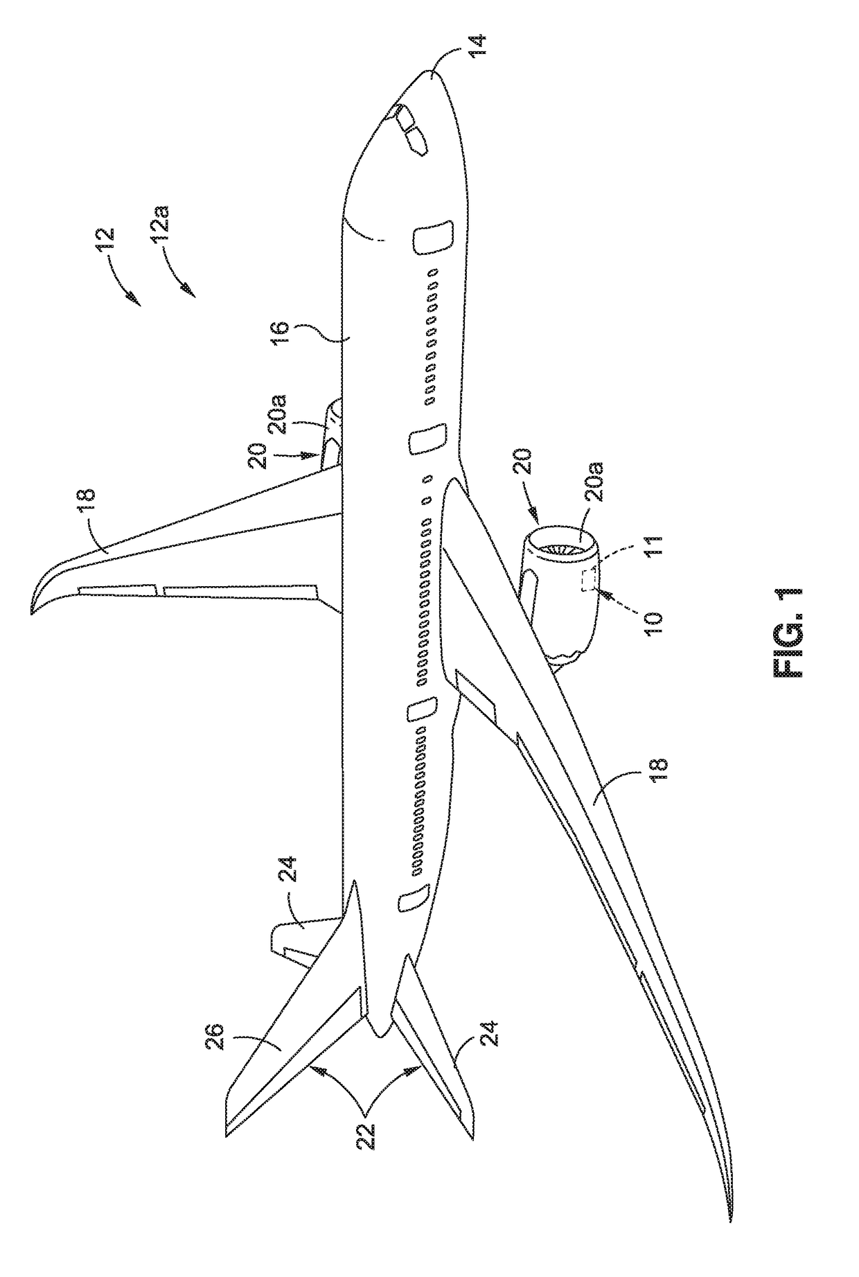
[0042]Now referring to the Figures, FIG. 1 is an illustration of a perspective view of a vehicle 12, such as in the form of an air vehicle 12a, incorporating an exemplary embodiment of a power extraction system 10, such as a combined HP / LP spool power extraction system 11, of the disclosure. As shown in FIG. 1, the vehicle 12, such as in the form of air vehicle 12a, comprises a nose 14, a fuselage 16, one or more wings 18, one or more gas turbine engines 20, such as in the form of one or more multi-spool gas turbine engines...


PUM


Abstract

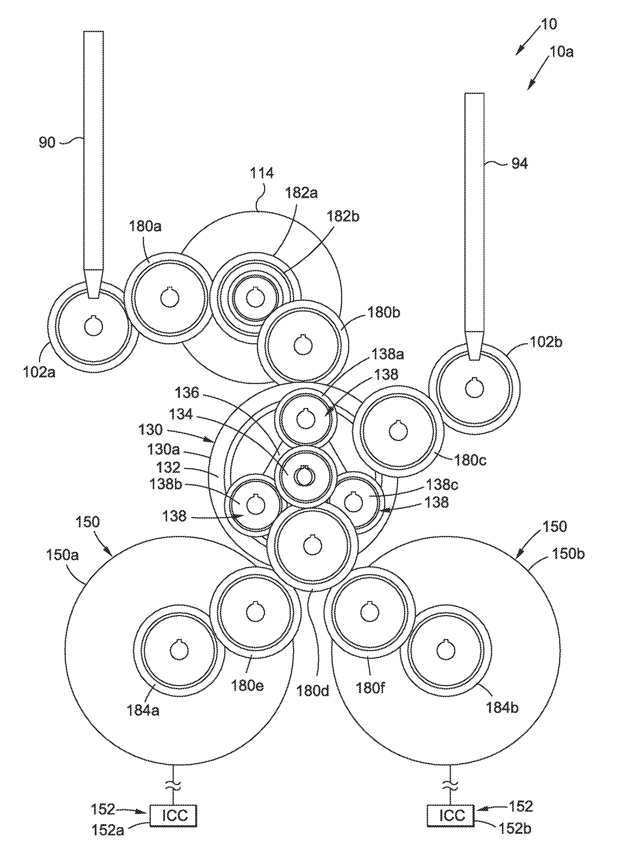
A power extraction system and method for a gas turbine engine of a vehicle are provided. The system has an HP spool tower shaft coupled between an HP spool of the gas turbine engine and an accessory gearbox assembly coupled to the gas turbine engine. The HP spool tower shaft extracts mechanical power from the HP spool. The system has an LP spool tower shaft coupled between an LP spool of the gas turbine engine and the accessory gearbox assembly. The LP spool tower shaft extracts mechanical power from the LP spool. The system further has the accessory gearbox assembly having an accessory drive combining the mechanical power from both the HP spool and LP spool, having a planetary gear train coupled to the accessory drive, and having one or more engine-driven accessories coupled to the planetary gear train and driven by a planetary gear train output to generate power.

Description

GOVERNMENT STATEMENT[0001]This invention was made with Government support under FA8650-11-2-2138, FA8650-08-D-3857 awarded by the Department of Defense. The Government has certain rights in this invention,BACKGROUND1) Field of the Disclosure[0002]The disclosure relates generally to systems and methods for power extraction from gas turbine engines, and more particularly, to systems and methods for mechanical power extraction from both the high pressure (HP) spool and low pressure (LP) spool of multi-spool gas turbine engines of vehicles, such as aircraft, rotorcraft, and other vehicles.2) Description of Related Art[0003]Gas turbine engines in vehicles, such as air vehicles, including aircraft and rotorcraft, as well as in vehicles, such as watercraft, automobiles, and other types of vehicles, may be in the form of multiple spool (i.e., “multi-spool”) gas turbine engines having a high pressure (HP) spool and a low pressure (LP) spool, where “spool” means a rotating assembly having a r...

Claims


Application Information

Patent Timeline
IPC IPC(8): F02C7/32B64D27/12F16H37/06
CPCF02C7/32B64D27/12F05D2260/40311F05D2220/323F16H37/065B64D33/00B64D2013/0618B64D2221/00Y02T50/50Y02T50/60F02C7/36
Inventor HOWELL, ERIC A.ROACH, JEFFREY M.OMOHUNDRO, THOMAS W.
Owner THE BOEING CO
Learn More