
Device and method for generating steam

a technology of generating device and steam, which is applied in the direction of steam generation, flash steam boiler, lighting and heating apparatus, etc. it can solve the problems of large steam rate, difficult to achieve large steam rate in a limited space, and increase the likelihood of scale on the interior surface, so as to achieve easy manner, the effect of generating more steam per unit tim

Active Publication Date: 2018-05-24
VERSUNI HLDG BV
View PDF8 Cites 10 Cited by
  • Summary
  • Abstract
  • Description
  • Claims
  • Application Information

AI Technical Summary

Benefits of technology

The patent is about a device that sprays water to improve heating and generate steam. The device has a chamber with a water receiving arrangement to make sure the water is spread evenly on the surfaces it comes into contact with. This results in more effective heating and more steam produced per unit time. Additionally, the device can cool down and then re-heat to remove any scale or other buildup that may accumulate on the surfaces during use. This buildup can decrease the efficiency of the device, but the method described in the patent makes it easy to remove and collect the scale.

Problems solved by technology

Due to constraints of size and weight for such a product, such steamers tend to produce only limited amount of steam.
For instantaneous steam generation in handheld steamers, large steam rates are harder to achieve in a limited space because this requires managing large volumes of water and energy extraction instantly within the aforementioned limited space.
However, a higher steam rate leads to more scale whenever hard natural water is involved, and the steam rate optimised “labyrinth” designs of flow-through heaters may often end up getting clogged with scale rather quickly.
Since the inside of such flow-through heaters cannot be accessed, the clogging cannot be removed / cleaned, leading to the product becoming non-functional.

Method used


Image

  • Device and method for generating steam
  • Device and method for generating steam
  • Device and method for generating steam

Examples


Embodiment Construction

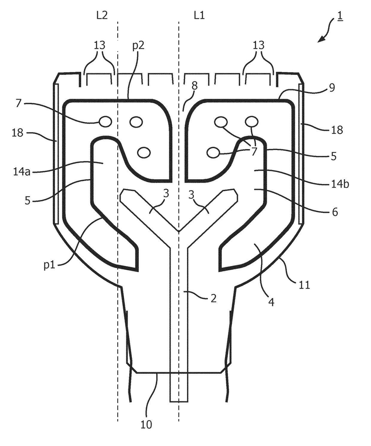
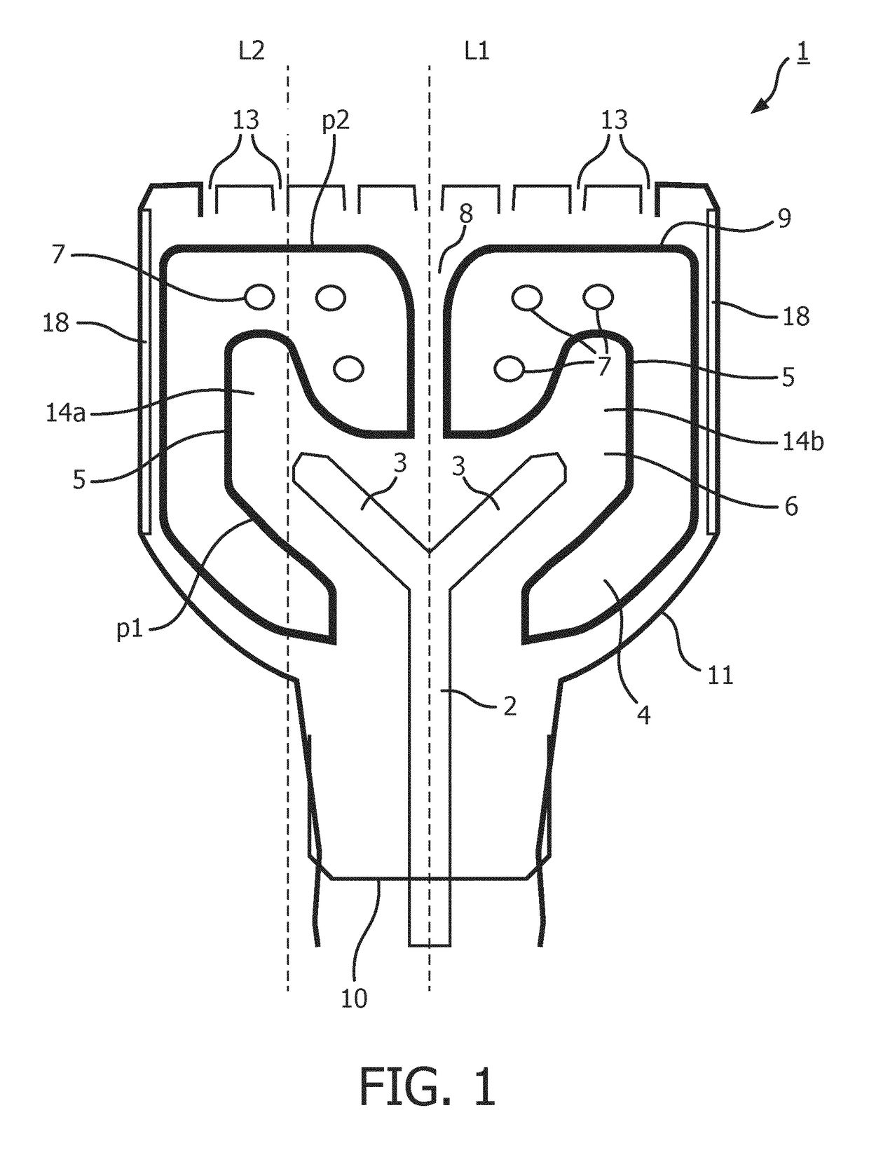
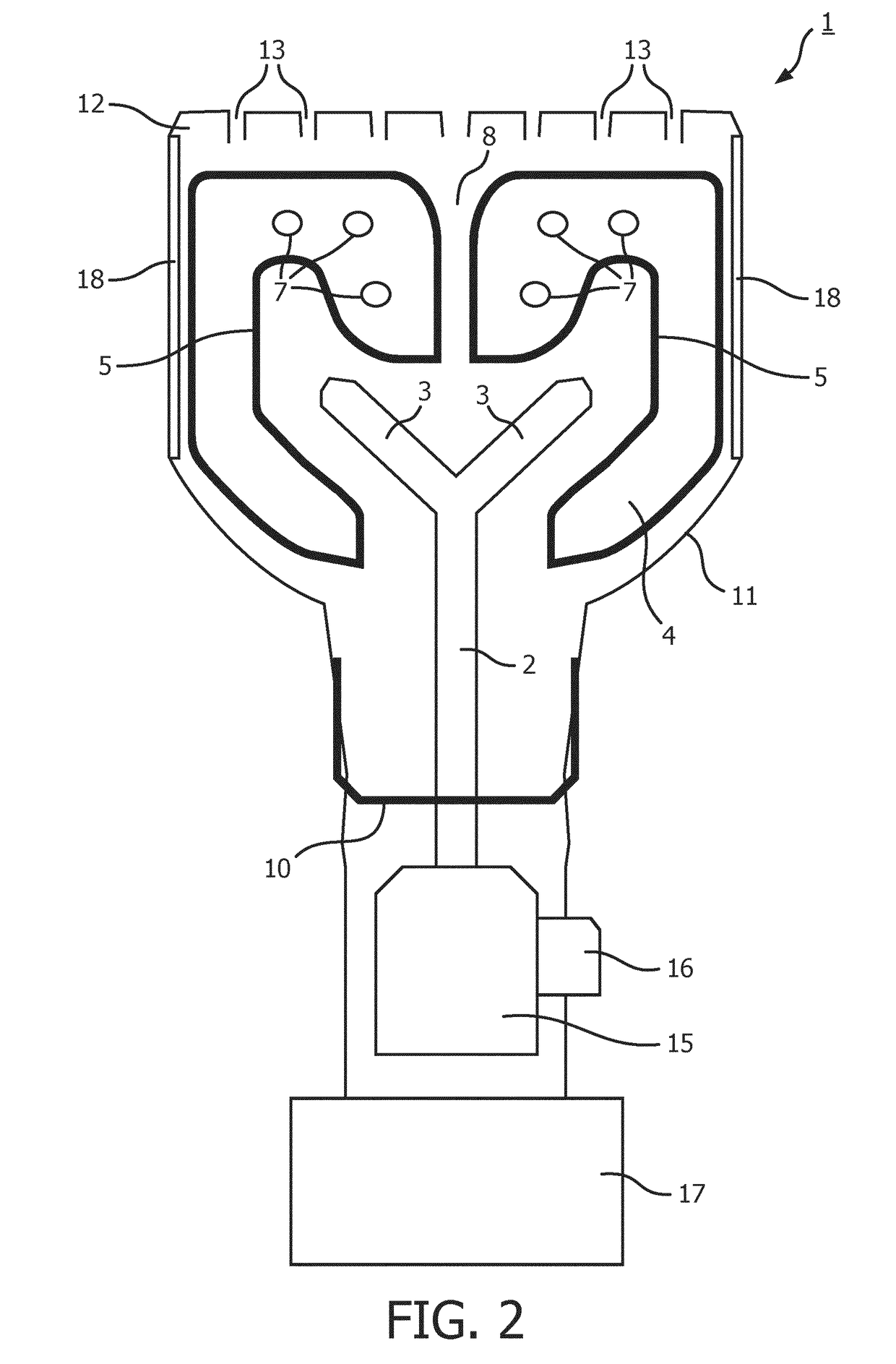
[0029]A device (1) according to an embodiment of the invention for generating steam is shown in FIGS. 1 and 2. The device (1) is in the form of a hand-held steamer.

[0030]The device (1) comprises a water outlet arrangement (2) having at least one open end (3) to spray water. The device (1) also comprises a water receiving arrangement (4) surrounding the at least one open end (3). The water receiving arrangement (4) comprises at least one interior surface (5) defining a chamber (6) in which the at least one open end (3) are arranged so that water sprayed from the at least one open end (3) is sprayed on the at least one interior surface (5). The device (1) further comprises at least one heating element (7) for heating the at least one interior surface (5) up to a temperature for generating steam from water sprayed on the at least one interior surface (5).

[0031]Liquid water is sprayed from the water outlet arrangement (2) through the at least one open end (3) onto the at least one inter...


PUM


Abstract

The invention relates to a device (1) for generating steam. The device (1) comprises a water outlet arrangement (2) having an open end (3) to spray water onto a water receiving arrangement (4). The water receiving arrangement (4) comprises an interior surface (5) defining a chamber (6) in which the open end (3) is arranged so that water sprayed from the open end (3) is sprayed onto the interior surface (5). The device further comprises a heating element (7) for heating the interior surface (5) up to a temperature for generating steam from water sprayed on the interior surface (5). The interior surface (5) is formed by two separate cavities (14a, 14b), the open end (3) comprising a spray nozzle (2) received within each cavity (14a, 14b) so that each spray nozzle (2) sprays water onto a region of the interior surface (5), each region being defined by the cavity (14a,14b) in which a respective spray nozzle (2) is received. This allows the water sprayed by the water outlet arrangement (4) be more uniformly spread on the interior surface (5), leading to more effective heating and more steam may be generated per unit time.

Description

FIELD OF THE INVENTION[0001]The present invention relates to a device for generating steam as well as to a corresponding method of generating steam.BACKGROUND OF THE INVENTION[0002]A handheld steamer typically comprises a small water tank, a low flow pump and a lower power steam generation unit in the same handle. In most handheld steamers, the mechanism for steam generation is flash boiling or flow-through heating, depending on the steam rate, wherein steam is produced on demand by pumping i.e. by dosing water over a hot surface. Steam vents nearby then let the steam out onto the garment. Due to constraints of size and weight for such a product, such steamers tend to produce only limited amount of steam.[0003]For instantaneous steam generation in handheld steamers, large steam rates are harder to achieve in a limited space because this requires managing large volumes of water and energy extraction instantly within the aforementioned limited space. Flow-through heating is often used...

Claims


Application Information

Patent Timeline
Patent Type & Authority Applications(United States)
IPC IPC(8): F22B27/16F22B1/28
CPCF22B27/16F22B1/282F22B1/288F22B1/287
Inventor WADHWA, SAHILJIANG, YONGBRUGGINK, WILHELMUS HENDRIKUS MARIALEE, CHEN-SHIANG
Owner VERSUNI HLDG BV
Learn More