
Anti-vibration mount for an in-vehicle video display

a video display and anti-vibration technology, which is applied in the direction of vehicle components, transportation and packaging, etc., can solve the problems of affecting the viewing experience, and affecting the stability of the video display, so as to reduce the risk of damaging the mounting screw hole, enhance the viewing experience, and eliminate the effect of vibration

Inactive Publication Date: 2018-05-24
NEWMAN JOSEPH
View PDF0 Cites 8 Cited by
  • Summary
  • Abstract
  • Description
  • Claims
  • Application Information

AI Technical Summary

Benefits of technology

The patent describes a mount for a video display in a vehicle that reduces vibration to make the video easier to watch and prevents damage to the mounting screw holes. The technical effect is a more comfortable and reliable viewing experience for the video in the vehicle.

Problems solved by technology

The constant vibration and bouncing caused by the movement of the vehicle can place significant stress on the screw interface between the VESA mount and the video display.
Over time, this can loosen the screws that attach the video display to the VESA mount, or worse, can actually damage the video display housing so that it becomes impossible to secure the video display to the VESA mount.
In a moving vehicle, this can result in excessive vibration of the display device that can make an image on the display device difficult to view.
For example, if a user is attempting to read a newspaper article, excessive vibration of the video display can make the text of the article difficult to read.

Method used


Image

  • Anti-vibration mount for an in-vehicle video display
  • Anti-vibration mount for an in-vehicle video display
  • Anti-vibration mount for an in-vehicle video display

Examples


Embodiment Construction

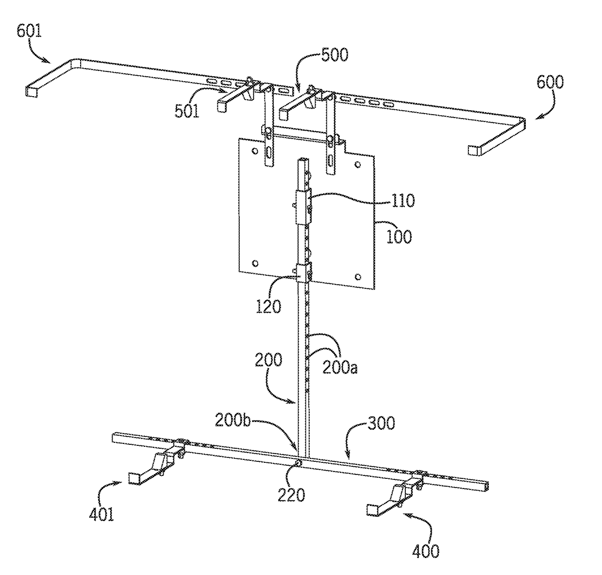
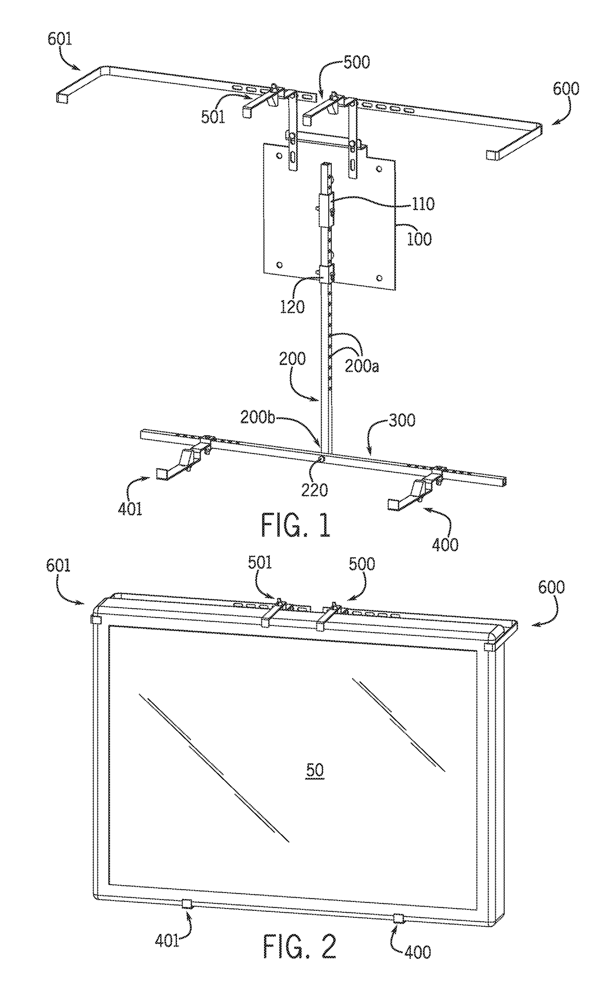
[0037]FIGS. 1 and 2 are front perspective views of an exemplary implementation of the ANTI-VIBRATION MOUNT FOR AN IN-VEHICLE VIDEO DISPLAY that includes bottom cradle arms 400, 401, top cradle arms 500, 501, and side cradle arms 600, 601 that adjustably support a video display 50, that effectively eliminate the risk of damaging the mounting screw holes in a video display 50, and that reduce vibration of the video display 50 to enhance the viewing experience.

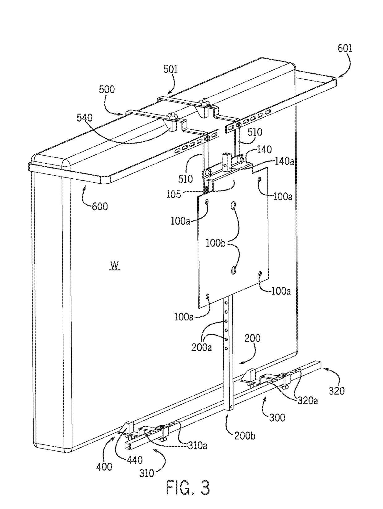
[0038]FIGS. 1, 3, and 4 show a base plate 100 of the ANTI-VIBRATION MOUNT FOR AN IN-VEHICLE VIDEO DISPLAY. As best shown in the exploded view of FIG. 4, the base plate 100 can have a generally square configuration with a protrusion 105 vertically extending from an upper portion of the base plate 100. In alternative exemplary implementations, the base plate may have a generally rectangular shape, and / or may lack the protrusion 105.

[0039]The base plate 100 includes a horizontal flange 140 extending from an upper portion of the base...


PUM


Abstract

An anti-vibration mount for an in-vehicle video display is disclosed for supporting a display device inside a moving vehicle so as to allow the display device to be attached to a mounting surface inside the vehicle without use of the mounting holes of the display device. The anti-vibration mount includes a base plate that directly connects to a mounting surface inside the vehicle. A plurality of adjustable support arms connected to the base plate securely hold the display device, and reduce vibration of the display device caused by vibration of the mounting surface in the vehicle.

Description

FIELD OF INVENTION[0001]This invention generally relates to mountings for video displays, and more particularly to a mount for mounting a video display inside a vehicle.BACKGROUND[0002]The ever decreasing size of video displays has made their deployment in vehicles a matter of inevitability. Nowadays, video displays are ubiquitous—they can be found in all manners of vehicles such as aircraft, passenger cars, police cars, trucks, vans, and taxicabs. These video displays often use the VESA Mounting Interface Standard (MIS) known colloquially as the VESA mount. The VESA mount is a family of standards defined by the Video Electronics Standards Association for mounting video displays such as flat panel monitors, TVs, and other displays to stands or wall mounts. It is implemented on most modern flat-panel monitors and TVs. Most sizes of VESA mount have four screw-holes arranged in a square on the mount, with matching mounting screw holes in the video display. While the VESA mount works to...

Claims


Application Information

Patent Timeline
Patent Type & Authority Applications(United States)
IPC IPC(8): B60R11/02
CPCB60R11/0235B60R2011/008B60R2011/0003
Inventor NEWMAN, JOSEPH
Owner NEWMAN JOSEPH
Learn More