
Wavelength converter

a wavelength converter and converter technology, applied in the direction of instruments, mountings, spectral modifiers, etc., can solve the problems of affecting and the substrate generating loud wind noise, etc., to achieve the effect of improving the excitation efficiency of fluorescent elements

Inactive Publication Date: 2018-05-17
DELTA ELECTRONICS INC
View PDF4 Cites 2 Cited by
  • Summary
  • Abstract
  • Description
  • Claims
  • Application Information

AI Technical Summary

Benefits of technology

Technical effects: The invention is a wavelength converter that improves the efficiency of exciting a fluorescent element, while reducing heat accumulation to prevent thermal decay. The converter has a design that prevents wind noise and windage. The light transmission member is embedded in a hollow hole in the substrate, which eliminates the need for a retaining wall structure and increases heat dissipation area and efficiency.

Problems solved by technology

The design of the wavelength converter applied in a 1-chip projector is more complicated.
However, the shape of the outer edge the substrate with the through hole design is not a perfect circle, so the substrate generate loud wind noise while rotating.
Otherwise, the motor may be easily damaged, and the bad rotating balance will cause vibration and noise.
In other words, the substrate with the through hole design has disadvantages of load noise arid bad rotating balance.
However, the piece of glass is adhered to the drive shaft of the motor o other component, so the piece of glass may fly out in the case of high-speed rotation, and the probability of the separation of the piece of glass is getting higher along with the increased radius of the substrate.
Once the piece of glass separates, the whole projector may be destroyed.
Moreover, owing to the small thermal conductivity of the glass, the substrate with the glass composite design also has the disadvantage of poor cooling effect.

Method used


Image

  • Wavelength converter
  • Wavelength converter
  • Wavelength converter

Examples


Embodiment Construction

[0029]Reference will now be made in detail to the present embodiments of the disclosure, examples of which are illustrated in the accompanying drawings. Wherever possible, the same reference numbers are used in the drawings and the description to refer to the same or like parts.

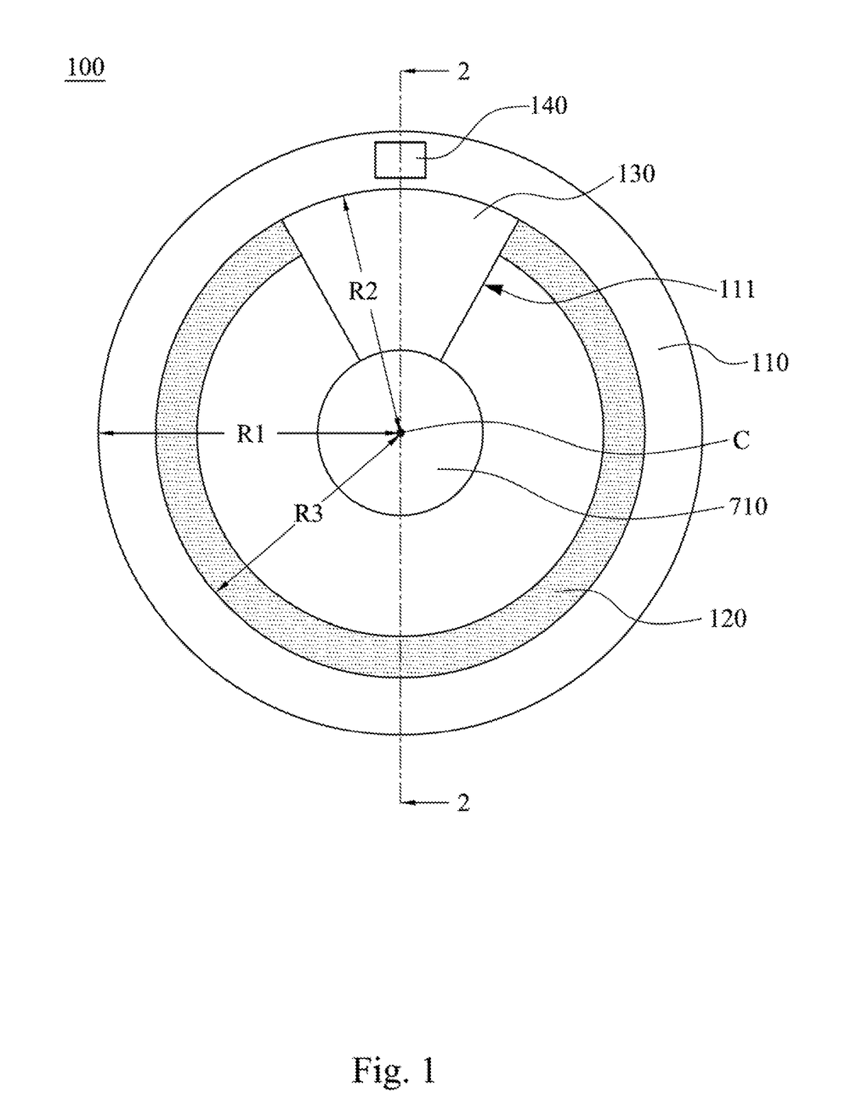
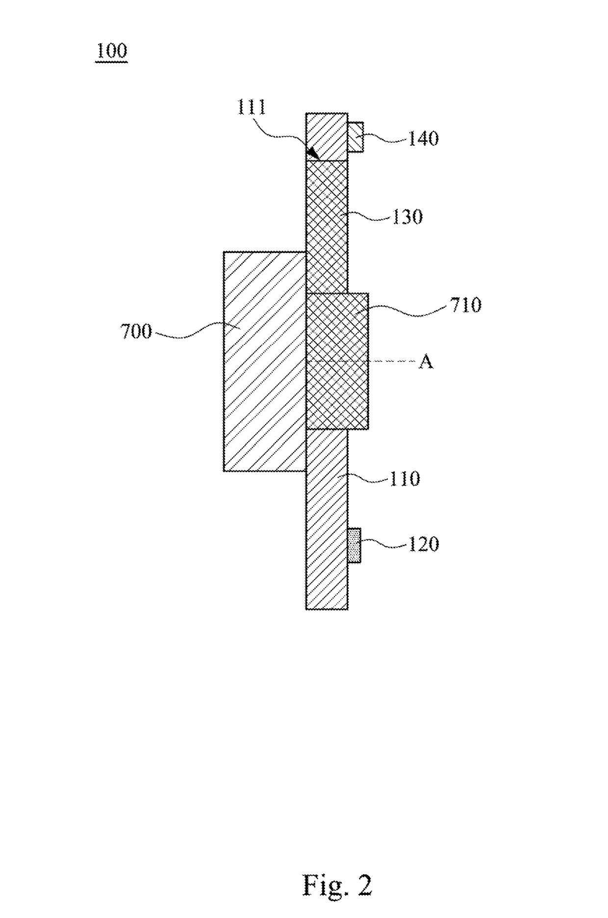
[0030]Reference is made to FIGS. 1 and 2. FIG. 1 is a front view of a wavelength converter 100 according to an embodiment of the disclosure. FIG. 2 is across-sectional view of the wavelength converter 100 in FIG. 1 taken along line 2-2. As shown in FIGS. 1 and 2, in the embodiment, the wavelength converter 100 includes a substrate 110, a phosphor layer 120, and a light transmission member 130. The substrate 110 is sleeved onto a drive shaft 710 of a motor 700 and has a hollow hole 111 The hollow hole 111 is located within an outer edge of the substrate 110. The phosphor layer 120 is disposed on the substrate 110 and adjoins the hollow hole 111. The light transmission member 130 is embedded in the hollow hole ...


PUM


Abstract

A wavelength converter includes a substrate, a phosphor layer, a light transmission member, and a centroid adjustment member. The substrate is configured to be sleeved onto a drive shaft of a motor and has a hollow hole located within an outer edge of the substrate. The phosphor layer is disposed on the substrate and adjoins, the hollow hole. The light transmission member is embedded in the hollow hole. The centroid adjustment member is disposed on the substrate and located outside an outer edge of the phosphor layer and an outer edge of the light transmission ember An equivalent centroid of a combination of the substrate, the phosphor layer, the light transmission member, and the centroid adjustment member is substantially located on the axis of the drive shaft.

Description

RELATED APPLICATIONS[0001]This application claims priority to Taiwan Application Serial Number 105137034, filed Nov. 14, 2016, which is herein incorporated by reference.BACKGROUNDTechnical Field[0002]The present disclosure relates to a wavelength converter, and more particularly, to a color wheel applied in a projector.Description of Related Art[0003]A phosphor wheel is a wavelength converter and is a key optical component in a laser projector, so as to convert laser light sources into fluorescent light sources. After the wavelength converting material on the phosphor wheel absorbs a certain range of wavelengths, internal electrons transition from ground state to excited state and release energy by way of releasing photons and phonons. Photon conversion means that the excited state electrons release photons having other wavelengths as light sources of the projector while transitioning to the ground state. Phonon conversion means that the excited state electrons release energy by way...

Claims


Application Information

Patent Timeline
Patent Type & Authority Applications(United States)
IPC IPC(8): G02B26/00F21V9/16G02B7/00
CPCG02B26/008F21V9/30G02B7/008F21V9/16
Inventor CHANG, KEH-SULU, CHUN-HSIENCHOU, YEN-ICHEN, CHI
Owner DELTA ELECTRONICS INC
Learn More