
Light curtain safety system

a technology of safety system and light curtain, applied in the field of detection of objects, can solve problems such as burns or other damage to non-living objects

Active Publication Date: 2018-05-17
LASERMOTIVE
View PDF3 Cites 23 Cited by
  • Summary
  • Abstract
  • Description
  • Claims
  • Application Information

AI Technical Summary

Benefits of technology

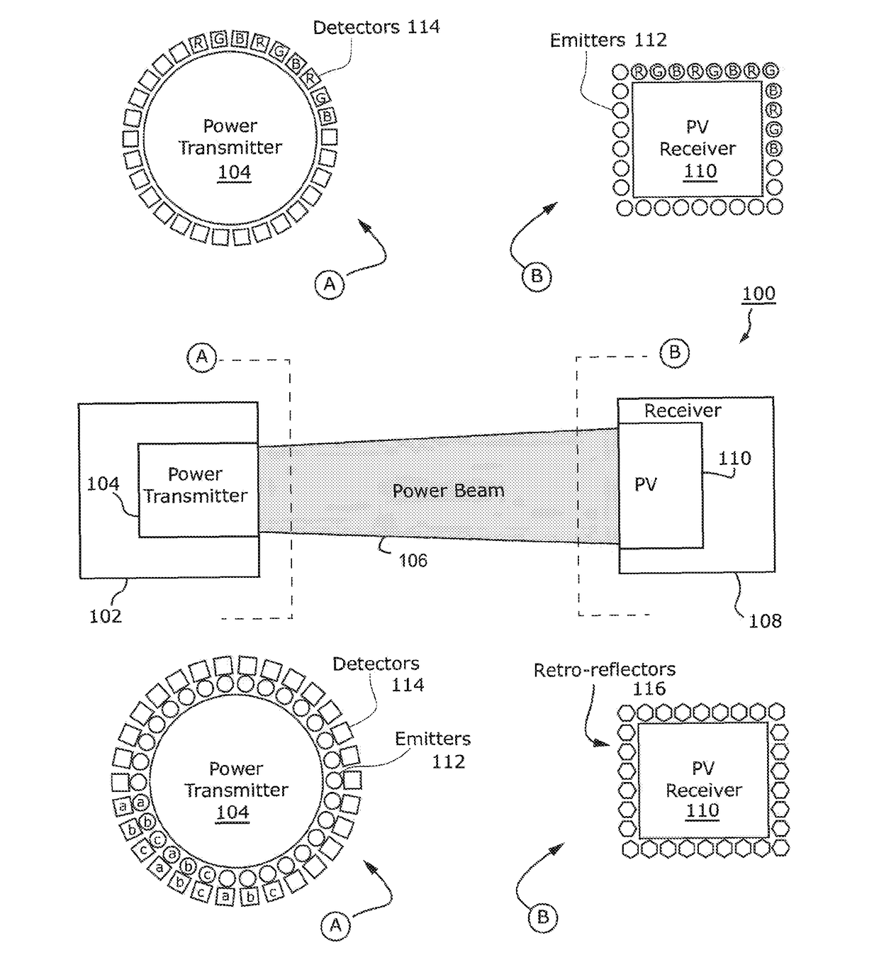
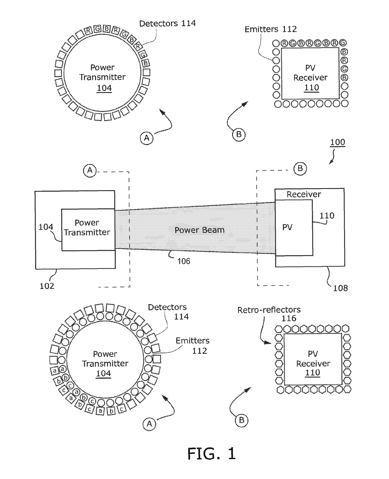
[0013]In some embodiments, the problem of receiving a guard beam light signal at a detector from a non-corresponding emitter, which masks detection of a foreign object intruding into the line-of-sight path between the detector and its corresponding emitter, is solved by providing a means of distinguishing the guard beam light signal of one emitter from the guard beam light signal of another emitter.

Problems solved by technology

In addition to eye or other tissue damage, the high-flux power beam may also cause burns or other damage to non-living objects.

Method used


Image

  • Light curtain safety system
  • Light curtain safety system
  • Light curtain safety system

Examples


Embodiment Construction

[0062]The present application is related to the following applications filed on the same day as the present application, naming the same inventors, and assigned to the same entity; each of said applications incorporated herein by reference to the fullest extent allowed by law: U.S. patent application Ser. No. ______, entitled MULTI-LAYERED SAFETY SYSTEM, bearing client number 720173.405; U.S. patent application Ser. No. ______, entitled DIFFUSION SAFETY SYSTEM, bearing client number 720173.407; U.S. patent application Ser. No. ______, entitled POWER BEAMING VCSEL ARRANGEMENT, bearing client number 720173.408; U.S. patent application Ser. No. ______, entitled LOCATING POWER RECEIVERS, bearing client number 720173.409; U.S. patent application Ser. No. ______, entitled MULTISTAGE WIRELESS POWER, bearing client number 720173.410.

[0063]In the following description, certain specific details are set forth in order to provide a thorough understanding of various disclosed embodiments. Howeve...


PUM


Abstract

A system to detect obstacles includes a power beam transmission circuit, a power beam reception circuit arranged to receive a power beam from the power beam transmission circuit, an emitter module, and a detector module arranged to distinguish between a first characteristic and a second characteristic. The emitter module includes a first emitter arranged to emit a first signal having the first characteristic, the first signal emitted in proximity to the power beam, and a second emitter arranged to emit a second signal having the second characteristic, the second characteristic different from the first characteristic, the second signal emitted in proximity to the first signal. The detector module includes a first detector arranged to respond to the first signal emitted by the first emitter, wherein the detector module is arranged to determine when an obstacle is in or near a line-of-sight transmission path between the first emitter and the first detector.

Description

CROSS-REFERENCE TO RELATED APPLICATION[0001]This application claims the benefit under 35 U.S.C. § 119(e) of U.S. Provisional Patent Application No. 62 / 163,307, filed on May 18, 2015, entitled “Provisional Patents for Wireless Power” which is hereby incorporated by reference in its entirety.BACKGROUNDTechnical Field[0002]The present disclosure generally relates to detection of objects in or around a hazardous area. More particularly, but not exclusively, the present disclosure relates to a light curtain safety system around a high-flux power beam or field.Description of the Related Art[0003]One form of remote power is a laser power beaming system. A laser power beaming system, also called an optical wireless power system, includes at least one transmitter and at least one corresponding receiver. The transmitter forms a high-flux beam of laser light, which is projected through the air over a distance toward the receiver.[0004]In conventional laser power beaming systems, the transmitte...

Claims


Application Information

Patent Timeline
Patent Type & Authority Applications(United States)
IPC IPC(8): G01V8/22H02J50/30H02J50/60G01S17/04G01S17/87G01S17/89
CPCG01V8/22H02J50/30H02J50/60G01S17/87G01S17/88G01S7/006G01S7/484H01S5/005H01S5/06216H01S5/423H04B10/807H04B10/1141G01S17/04Y02E10/52G01S17/89G01S7/003H02J50/10H01S5/0085H02J50/90G01S17/06
Inventor KARE, JORDIN T.NUGENT, JR., THOMAS J.BASHFORD, DAVIDERICKSON, CARSTEN CASEYBASHFORD, THOMAS W.
Owner LASERMOTIVE
Learn More