
Vehicle rear region image display device, and non-transitory computer-readable medium storing vehicle rear region image display program

a technology for rear region images and display devices, which is applied in vehicle components, color television details, television systems, etc., can solve the problems of unnatural shake correction, incongruity of vehicle occupants with the displayed image of the display section, etc., and achieve the effect of suppressing the feeling of incongruity

Inactive Publication Date: 2018-05-10
TOYOTA JIDOSHA KK
View PDF5 Cites 2 Cited by
  • Summary
  • Abstract
  • Description
  • Claims
  • Application Information

AI Technical Summary

Benefits of technology

The present patent provides a device and program for displaying images of a vehicle's rear region. The device can detect when the vehicle occupant sways due to vibrations and adjust the position of the displayed image to match this timing. This results in a less noticeable display shake and reduces the feeling of incongruity between the image and the vehicle occupant's movements. Overall, the device and program improve the overall experience of driving and viewing the vehicle's rear region images.

Problems solved by technology

Therefore, the timing at which the vehicle occupant sways due to vibrations and the timing at which the image shakes are offset from one another, and thus, there is the concern that the vehicle occupant will feel a sense of incongruity to the displayed image of the display section.
Namely, in a case of vibrations that are equal to or greater than the frame rate of the imaging section are input, shake correction cannot be carried out with respect to vibrations that are of a timing corresponding to the interval between image frames, and therefore, shake correction becomes unnatural.

Method used


Image

  • Vehicle rear region image display device, and non-transitory computer-readable medium storing vehicle rear region image display program
  • Vehicle rear region image display device, and non-transitory computer-readable medium storing vehicle rear region image display program
  • Vehicle rear region image display device, and non-transitory computer-readable medium storing vehicle rear region image display program

Examples


Embodiment Construction

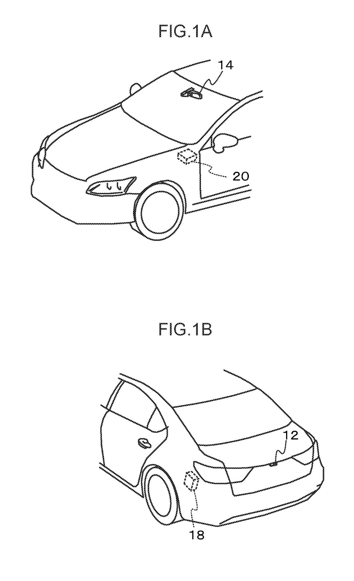
[0025]An example of an embodiment of the present disclosure is described in detail hereinafter with reference to the drawings. FIG. 1A is a drawing illustrating an installed position in a vehicle, at the vehicle front side, of a vehicle rear region image display device relating to a present exemplary embodiment, and FIG. 1B is a drawing illustrating the vehicle rear side.

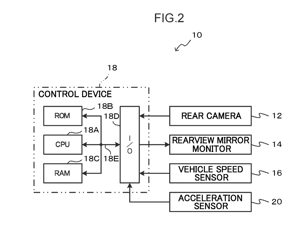
[0026]The vehicle rear region image display device relating to the present exemplary embodiment captures images of the vehicle rear region by a rear camera 12 that serves as an example of an imaging section that is provided at the vehicle rear portion, and displays the captured images on a rearview mirror monitor 14 that serves as an example of a display section and is provided at the position of the rearview mirror within the vehicle cabin. By providing the rearview mirror monitor 14 at the position of the rearview mirror, the rearview mirror monitor 14 may function as the rearview mirror.

[0027]Further, an accelera...


PUM


Abstract

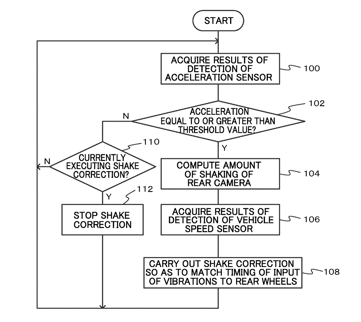
The present disclosure provides a vehicle rear region image display device that may suppress a sense of incongruity to a displayed image, due to offset in timings between a timing at which a vehicle occupant sways due to vibrations and a timing at which the displayed image of a display section shakes. Namely, an acceleration sensor, which detects acceleration as a physical amount corresponding to an amount of displacement in a vehicle vertical direction of a rearview mirror monitor due to vibrations inputted to front wheels of a vehicle, is provided in a vicinity of the rearview mirror monitor. On the basis of results of detection of the acceleration sensor, a control device computes an amount of shake of a rear camera, and carries out shake correction so as match a timing at which vibrations are inputted to rear wheels of the vehicle.

Description

CROSS-REFERENCE TO RELATED APPLICATION[0001]This application claims priority under 35 USC 119 from Japanese Patent Application No. 2016-218143, filed Nov. 8, 2016, the disclosure of which is incorporated by reference herein.BACKGROUNDTechnical Field[0002]The present disclosure relates to a vehicle rear region image display device and to a non-transitory computer-readable medium storing a vehicle rear region image display program, which are installed in a vehicle and display captured images of a vehicle rear region.Related Art[0003]There are known vehicle rear region image display devices that enable viewing of the rear region of a vehicle by capturing images of the rear region of the vehicle by an imaging section such as a camera or the like, and displaying the captured images on a display section, such as a monitor or the like that is within the vehicle cabin.[0004]For example, in the technique described in Japanese Patent Application Laid-Open (JP-A) No. 2009-100180, because the i...

Claims


Application Information

Patent Timeline
IPC IPC(8): B60R1/00H04N5/232
CPCB60R1/00B60R2300/8026B60R2300/60H04N5/23264H04N5/262H04N7/183B60R2300/802B60R2300/8066B60R2300/30B60R1/26B60R2300/302H04N23/683H04N23/682
Inventor AMANO, MASAAKIASAI, GOROKOCHIYA, TAKUMI
Owner TOYOTA JIDOSHA KK
Learn More