High-frequency dielectric heating device

Inactive Publication Date: 2018-04-19
TOYO SEIKAN GRP HLDG LTD
View PDF0 Cites 1 Cited by
  • Summary
  • Abstract
  • Description
  • Claims
  • Application Information

AI Technical Summary

Benefits of technology

This patent describes a method for improving the efficiency of a high-frequency power supply by detecting reflected power and adjusting the impedance matching using a capacitor. By varying the frequency of the power supply, the reactance of the capacitor can be adjusted at a high resolution, resulting in easy and precise impedance adjustment. The use of a semiconductor type high-frequency power supply can further enhance the responsive impedance matching and suppress damage to the power supply. Additionally, the provision of a matching device with a varier for continuous variation on the capacitance can allow for more effective suppression of reflected power and maintain stable heating or thawing of foodstuff. The use of a small, highly efficient semiconductor type high-frequency power supply and a third capacitor connected in parallel to the electrodes can also ensure stability during heating or thawing while suppressing variation in the electrode impedance.

Problems solved by technology

At this time, in a state where a difference exists between an output impedance of a high-frequency power supply and the electrode impedance when the heating subject is placed, or in other words when impedance matching has not been achieved, reflected power may be generated, leading to a reduction in heating or thawing efficiency, and as a result, a circuit element may break or deteriorate.
However, a vacuum tube type high-frequency power supply, due to a power amplification characteristic thereof, is large, has a high anode voltage, exhibits poor power supply efficiency, and has a high device cost due to the need to compensate for these problems by means of an increase in output.
Moreover, a filament must be preheated, meaning that it takes time to start the device.
Furthermore, a resonance frequency thereof varies unpredictably depending on the electrode impedance when the heating subject is placed.
More specifically, the power supply frequency affects a uniformity (power penetration depth) with which foodstuffs of various shapes are heated or thawed, and therefore, in certain conditions, the resonance frequency varies unpredictably, which is undesirable.
A state of matching impedance is maintained by successively varying a value of a variable capacitor or a variable coil serving as a constituent element of the matching device, but in the case of a large-capacity load such as a foodstuff, with which the electrode impedance varies greatly depending on the shape, type, and temperature thereof, the capacitor or coil must be provided with a large impedance adjustment width in order to maintain the matching state, and as a result, the matching device increases in size and cost.
However, in a configuration where the third capacitor C3 has a variable capacitance and the value thereof is varied successively, the electrode impedance also varies successively in accordance therewith, and therefore, particularly in a case where a large-capacity load such as a foodstuff is disposed between the electrodes 30 and the electrode impedance varies greatly depending on the shape, type, and heating or thawing temperature thereof, capacitance variation is promoted, making it difficult to perform impedance matching continuously with stability.
To maintain an impedance match in a state where the electrode impedance is unstable, the first capacitor C1 must be provided with a large impedance adjustment width, leading to increases in the size and cost of the matching device 40.

Method used


Image

  • High-frequency dielectric heating device
  • High-frequency dielectric heating device
  • High-frequency dielectric heating device

Examples


first example

[0077]A first experimental example of the present invention will now be described.

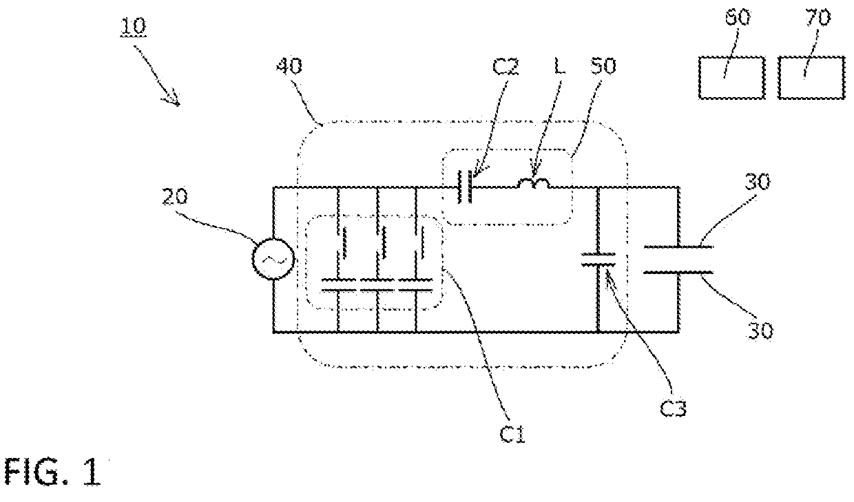
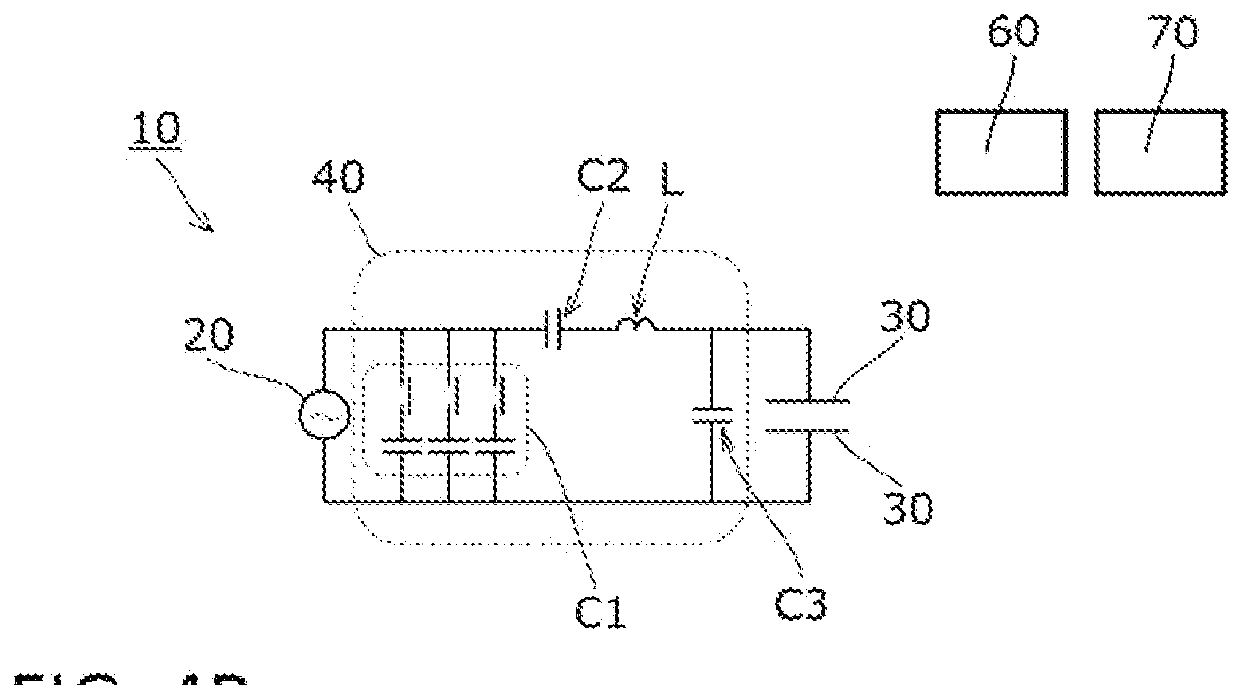
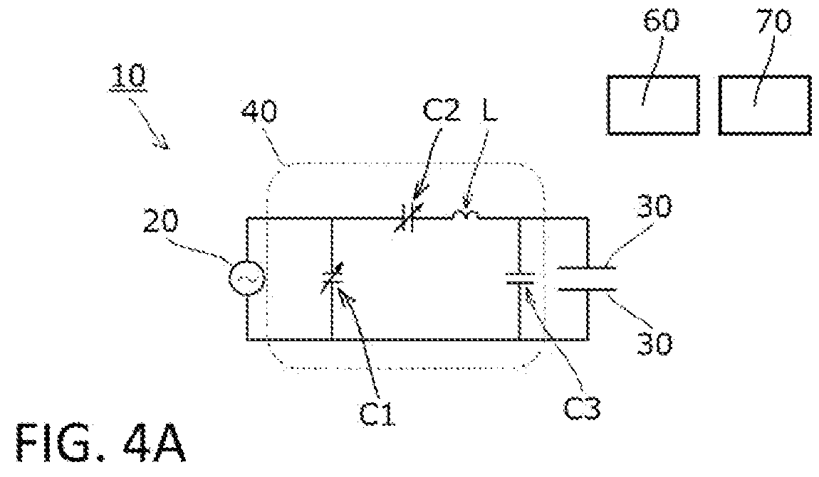
[0078]In the first experimental example, the capacitance of the second capacitor C2 of the reactance circuit 50 was set at 93 pF, the inductance of the coil L was set at 1.8 μH, and impedance adjustment was implemented on the reactance circuit 50 by adjusting the frequency of the high-frequency power supply 20. Further, the capacitance of the third capacitor C3 was set at 400 pF. Furthermore, the high-frequency power supply 20 was configured such that the high-frequency output thereof was stopped by the protective function when the reflectance detected by the reflected power detector 60 exceeded 40%. Moreover, frozen persimmons (four) were used as the thawing subject (heating subject) disposed between the pair of electrodes 30.

[0079]FIG. 3 shows results obtained by measuring the frequency and the reflectance every minute following the start of thawing.

[0080]When thawing was executed with the capacitanc...

second example

[0099]A second experimental example of the present invention will now be described.

[0100]FIG. 2A shows values (capacitance %) obtained when the frequency of the high-frequency power supply 20=13.56 MHz, the output impedance of the high-frequency power supply 20=50Ω, the capacitance C1 of the first capacitor C1=1500 pF, the capacitance C2 of the variable capacitance second capacitor C2=25 to 250 pF, the inductance L of the coil L=1.8 μH, and various foodstuffs were thawed while adjusting the capacitance of the second capacitor C2 so that the reflected power detected by the reflected power detector 60 was at a minimum at all times.

[0101]When the third capacitor C3 is not connected, the C2 capacitance % at the start of thawing differs depending on the type and number of the foodstuff, while the C2 capacitance % at the end of thawing varies greatly in the decreasing direction. In other words, it is difficult to implement impedance matching without increasing the capacitance variation wi...


PUM


Abstract

Provided is a high-frequency dielectric heating device in which fine impedance adjustment can be achieved easily and with high precision while reducing a device cost and simplifying a device structure. A high-frequency dielectric heating device (10) includes a high-frequency power supply (20), a pair of electrodes (30) disposed opposite each other, reflected power detector 60 connected between the electrodes (30) and the high-frequency power supply (20) and detects reflected power generated when a heating subject is heated, and an impedance matching device (40) that adjusts the reflected power, wherein the matching device (40) includes a capacitor (C1) connected in parallel to the high-frequency power supply (20), and at least one of a capacitor (C2) and a coil (L) connected in series to the electrodes (30), at least a reactance of the capacitor or the coil being adjustable, and the high-frequency power supply (20) is configured to have a variable frequency.

Description

TECHNICAL FIELD[0001]The present invention relates to a high-frequency dielectric heating device for heating a heating subject disposed between opposing electrodes by means of high-frequency dielectric heating, and more particularly to a high-frequency dielectric heating device for thawing a frozen foodstuff by means of high-frequency dielectric heating.BACKGROUND ART[0002]A high-frequency dielectric heating device that heats a heating subject disposed between opposing electrodes by means of high-frequency dielectric heating is available as a conventional high-frequency dielectric heating device for heating a heating subject by means of high-frequency dielectric heating (see Patent Literature 1, for example). High-frequency dielectric heating is a heating method in which a high-frequency voltage is applied to the heating subject (a dielectric) in order to vary respective polarities of molecules constituting the heating subject at a high frequency, and the heating subject is heated b...

Claims


Application Information

Patent Timeline
IPC IPC(8): H05B6/50H05B6/54
CPCH05B6/50H05B6/54H05B6/64
Inventor MARUYAMA, TOMOKIYAMADA, SHINJI
Owner TOYO SEIKAN GRP HLDG LTD
Why Eureka
Try Eureka