Bulk acoustic wave resonator with a mass adjustment structure and its application to bulk acoustic wave filter

Active Publication Date: 2018-04-19
WIN SEMICON
View PDF2 Cites 1 Cited by
  • Summary
  • Abstract
  • Description
  • Claims
  • Application Information

AI Technical Summary

Benefits of technology

The present invention provides a bulk acoustic wave resonator with a mass adjustment structure that increases its mechanical strength without affecting its overall flatness and suppresses spurious mode. The mass adjustment structure includes a supporting layer, lower metal layer, piezoelectric layer, upper metal layer, and a cavity. The mass adjustment structure is divided into a peripheral region and a central region and has a proper dimension to adjust the ratio of reflection acoustic wave and incident acoustic wave and enhance the Q factor of the resonator while suppressing spurious mode. The supporting layer also effectively enhances the mechanical structure strength of the resonator to avoid bending or collapsing under stress.

Problems solved by technology

Moreover, the insufficient mechanical strength of the resonance film of the bulk acoustic wave resonator may even result in collapse of the resonance film of the bulk acoustic wave resonator.
However forming the protruding structure along the edge of the top surface of the bottom electrode 91, the flatness of the piezoelectric layer 92 may be poor such that the entire flatness of the resonance film of the bulk acoustic wave resonator is affected.
Hence, the characteristics of the acoustic wave propagating in the resonance film of the bulk acoustic wave resonator may be affected so that the characteristics of the bulk acoustic wave resonator are adversely affected.

Method used


Image

  • Bulk acoustic wave resonator with a mass adjustment structure and its application to bulk acoustic wave filter
  • Bulk acoustic wave resonator with a mass adjustment structure and its application to bulk acoustic wave filter
  • Bulk acoustic wave resonator with a mass adjustment structure and its application to bulk acoustic wave filter

Examples


Embodiment Construction

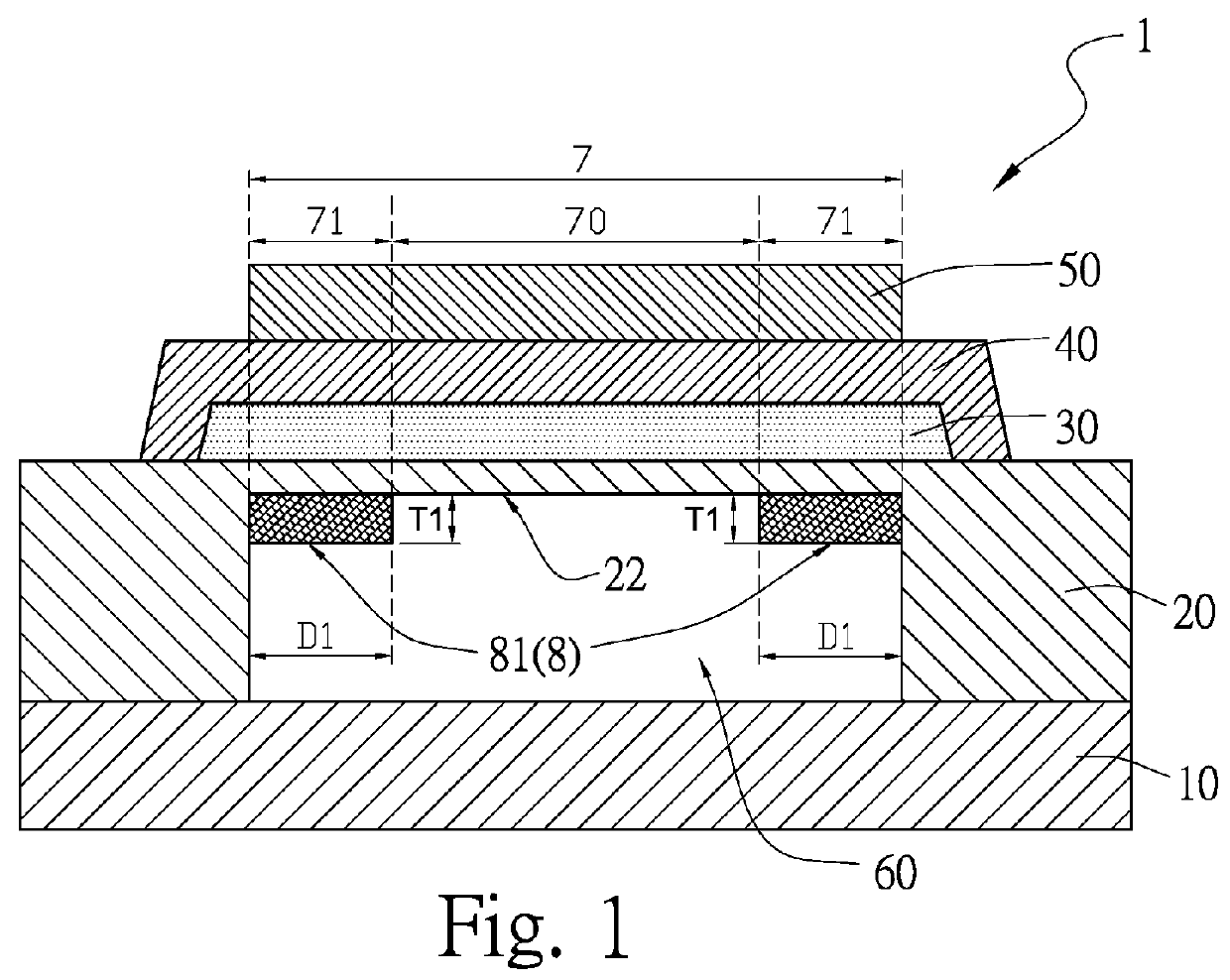
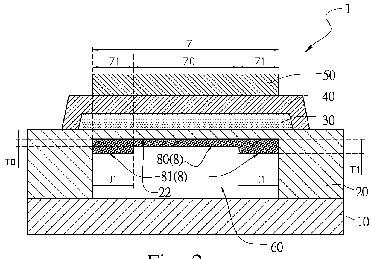
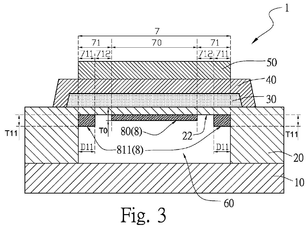
[0031]The present invention provides a bulk acoustic wave resonator with a mass adjustment structure, which comprises a supporting layer, a lower metal layer, a piezoelectric layer, an upper metal layer and a mass adjustment structure, wherein the supporting layer is formed on a substrate, wherein the supporting layer has a cavity; the cavity has a top-inner surface. The lower metal layer is formed on the supporting layer. The piezoelectric layer is formed on the lower metal layer. The upper metal layer is formed on the piezoelectric layer. An acoustic wave resonance region is defined by an overlapping region of projections of the upper metal layer, the piezoelectric layer, the lower metal layer, the supporting layer and the cavity, wherein the acoustic wave resonance region is divided into a peripheral region and a central region, wherein the peripheral region is divided into a first peripheral sub-region and a second peripheral sub-region, the second peripheral sub-region is betwe...


PUM


Abstract

A bulk acoustic wave resonator with a mass adjustment structure comprises a supporting layer, a lower metal layer, a piezoelectric layer, an upper metal layer and a mass adjustment structure. The supporting layer is formed on a substrate. The supporting layer has a cavity, and the cavity has a top-inner surface. The lower metal layer is formed on the supporting layer. The piezoelectric layer is formed on the lower metal layer. The upper metal layer is formed on the piezoelectric layer. An acoustic wave resonance region is defined by an overlapping region of projections of the upper metal layer, the piezoelectric layer, the lower metal layer, the supporting layer and the cavity. The acoustic wave resonance region is divided into a peripheral region and a central region. The mass adjustment structure comprises a peripheral mass adjustment structure formed on the top-inner surface within the peripheral region.

Description

FIELD OF THE INVENTION[0001]The present invention relates to a bulk acoustic wave resonator with a mass adjustment structure, which have the advantages of increasing the mechanical strength of the resonance film of the bulk acoustic wave resonator, enhancing the Q factor of the bulk acoustic wave resonator, and suppressing the spurious mode.BACKGROUND OF THE INVENTION[0002]Please refer to FIG. 10, which is a schematic view of an embodiment of a bulk acoustic wave resonator of the conventional technology. The resonator comprises a substrate 90, a bottom electrode 91, a piezoelectric layer 92, a top electrode 93, a cavity 94 and an annular piezoelectric layer recess 95. The bottom electrode 91 is formed on the substrate 90. The piezoelectric layer 92 is formed on the bottom electrode 91. The top electrode 93 is formed on the piezoelectric layer 92. The cavity 94 is formed under the bottom electrode 91 on the substrate 90. The overlapping of the top electrode 93, the piezoelectric laye...

Claims


Application Information

Patent Timeline
IPC IPC(8): H03H9/17H03H9/54
CPCH03H9/54H03H9/17H03H9/02118H03H9/02133H03H9/174H03H9/588H03H9/605H03H9/583
Inventor CHANG, CHIA-TACHIANG, CHIH-FENGHSIEH, TZU-SHENG
Owner WIN SEMICON
Why Eureka
Try Eureka