System and Method for Improving Fuel Mileage of Internal Combustion Engine

Inactive Publication Date: 2018-04-19
CEREMIS EDUARDAS
View PDF29 Cites 0 Cited by
  • Summary
  • Abstract
  • Description
  • Claims
  • Application Information

AI Technical Summary

Benefits of technology

The invention is about placing strong magnets in an engine's air intake to improve combustion efficiency and reduce pollution. The magnets are placed between layers of iron or other metal, which creates a magnetic field through which the air must flow. The presence of the magnets and iron or other metal increases the amount of airflow and the magnets are permanent, so no harmful substances are released during engine operation.

Problems solved by technology

It is known that gasoline and oxygen are the only two elements participating in the burning process of fuel whereby only 30% of the fuel is being used; 70% is wasted and is polluting our air.

Method used


Image

  • System and Method for Improving Fuel Mileage of Internal Combustion Engine
  • System and Method for Improving Fuel Mileage of Internal Combustion Engine
  • System and Method for Improving Fuel Mileage of Internal Combustion Engine

Examples


Embodiment Construction

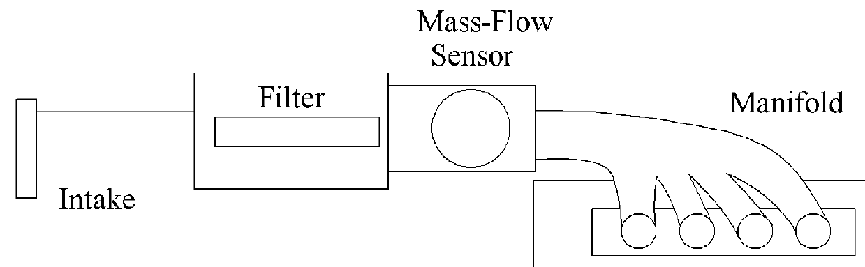
[0015]The present invention relates to a system and method for reducing fuel usage in internal combustion engines. It has been found experimentally, that if the air intake system to the engine is modified by placing a pair or multiple pairs of very strong permanent magnets in the airflow and forcing the air to flow between the magnets through the magnetic field, the engine may be run efficiently in a very lean fuel mode. The effect is enhanced if each magnet it coated with a thin layer of metallic iron.

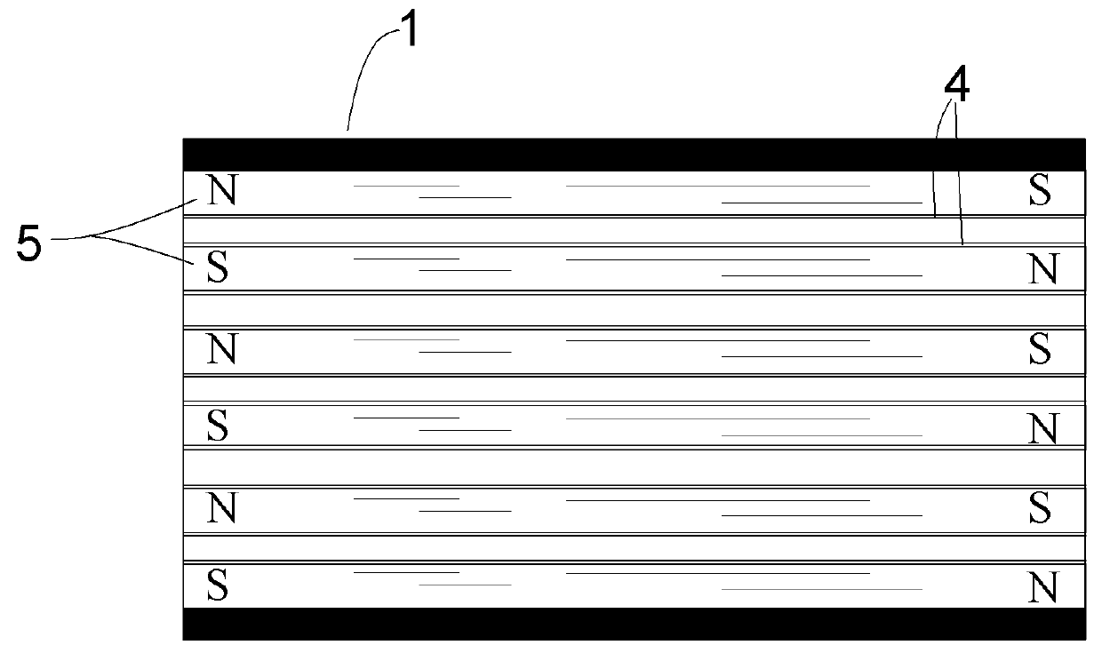
[0016]The preferred magnets are neodymium; however, any very strong magnets are within the scope of the present invention. The magnets are placed generally horizontally in pairs in the air intake system with the north pole of a first magnet aligned with a south pole of a second magnet. Each magnet can have a thin coating of metal different from the metal from which it is made from approximately 0.5 mm to 2.0 mm thick on the surface that faces the other magnet in the pair. The preferre...


PUM


Abstract

A modification to the air input ducting of an internal combustion engine. The engine can be gasoline, diesel or other fuel and can be located in any type of vehicle including automobiles, trucks, boats, ships, aircraft and any other vehicle. The invention includes mounting layers of very strong permanent magnets with interspersed iron or other metal structures in the air intake of the engine. The magnets are placed so that the intake air must flow between them through the strong magnetic field and at the same time contact the iron or other metal which is generally a surface layer on each magnet. The total amount of airflow is not impeded and is almost the same as when the magnets are not present. Pollution is also greatly reduced.

Description

BACKGROUNDField of the Invention[0001]The present invention relates to the field of internal combustion engines and more particularly to a system and method for improving fuel mileage.Description of the Problem[0002]It is well-known that internal combustion engines suffer from gross inefficiencies and get very poor fuel mileage. Over the years, there have been numerous suggestions and inventions aimed at improving this situation. Many of these partial solutions involve better carburetion or fuel-air mixing. Some solutions use pressure or compressed air. Vehicle computers are aimed at providing efficient mixing for various load conditions.[0003]It would be advantageous to have a system and method that made full use of the gas components of air to provide very efficient burning with very little fuel.SUMMARY OF THE INVENTION[0004]The present invention relates to a modification to the air input ducting of an internal combustion engine. The engine can be gasoline, diesel or other fuel an...

Claims


Application Information

Patent Timeline
IPC IPC(8): F02M27/04F02M35/10
CPCF02M35/10334F02M27/045
Inventor CEREMIS, EDUARDAS
Owner CEREMIS EDUARDAS
Why Eureka
Try Eureka