
Printing device

Active Publication Date: 2018-04-12
MIMAKI ENG
View PDF4 Cites 2 Cited by
  • Summary
  • Abstract
  • Description
  • Claims
  • Application Information

AI Technical Summary

Benefits of technology

This patent describes a printing device that can accurately transport a recording medium. The device uses a simple configuration with a moving section that detects and corrects any displacement during transportation. This ensures that the recording medium is fed accurately, resulting in high-quality printing without failures such as print lines. The device is also cost-effective because it uses a displacement sensor like a linear scale or encoder to detect displacement without measuring distance. Overall, this patent provides a solution for printing devices to achieve precise and efficient printing.

Problems solved by technology

However, the inkjet recording device of Japanese Unexamined Patent Publication No. 2015-13455 needs to arrange the detecting section on the gripping unit to detect the movement amount of the belt as the gripping unit is moved with the moving belt, the movement amount is measured by the detecting section, and the measured movement amount is detected as the movement amount of the belt, and hence simplification of the configuration is difficult.

Method used


Image

  • Printing device
  • Printing device
  • Printing device

Examples


embodiment

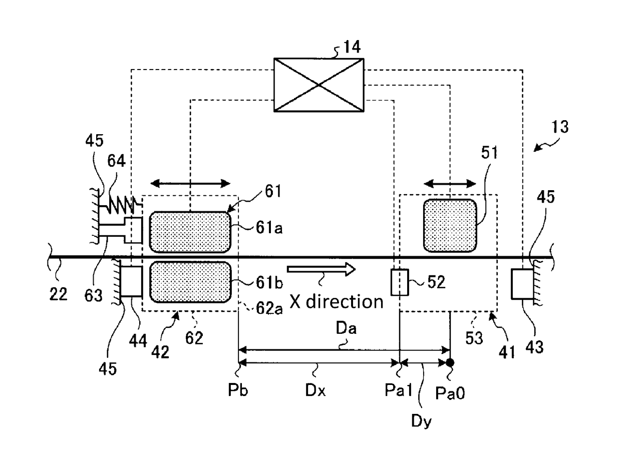
[0028]FIG. 1 is a schematic configuration view showing an inkjet device according to the present embodiment. FIG. 2 is a schematic configuration view showing a feed amount correcting unit of the inkjet device according to the present embodiment. FIG. 3 is a schematic view showing a displacement detection sensor. FIG. 4 is a schematic configuration view showing an operation of the feed amount correcting unit. FIG. 5 is a flowchart on one example of a control operation related to an origin point detection timing of a displacement sensor unit. FIG. 6 is a flowchart on one example of a control operation related to an origin point detection of the displacement sensor unit. FIG. 7 is a flowchart on one example of a preparatory operation before a feed control. FIG. 8 is a flowchart on one example of a feed control operation.

[0029]An inkjet device (printing device) 1 according to the present embodiment is a so-called inkjet type printer that discharges an ink liquid droplet from a plurality...


PUM


Abstract

To provide a printing device such as an inkjet device capable of transporting a recording medium at satisfactory precision with a simple configuration. The inkjet device includes a feed amount correcting section that corrects a feed amount of a recording medium, and a control section that controls the feed amount correcting section. The feed amount correcting unit includes a moving section that moves with a movement of the recording medium in a transporting direction and a displacement sensor section that detects a displacement amount of the moving section, and the control section controls the feed amount of the recording medium based on a difference between a feed amount acquired at a time of printing and a set feed amount set in advance.

Description

CROSS REFERENCE TO RELATED APPLICATIONS[0001]This application claims the priority benefit of Japanese Patent Application No. 2016-200219, filed on Oct. 11, 2016. The entirety of the above-mentioned patent application is hereby incorporated by reference herein and made a part of this specification.TECHNICAL FIELD[0002]The present disclosure relates to a printing device.DESCRIPTION OF THE BACKGROUND ART[0003]An inkjet recording device that mounts a recording medium such as a fabric on a belt, transports the recording medium in a feeding direction (transporting direction) by moving the belt, and discharges ink from an inkjet head to the transported recording medium to carry out printing is known (see e.g., Japanese Unexamined Patent Publication No. 2015-13455). Such an inkjet recording device includes a detecting section that continuously detects a movement amount of a gripping unit for gripping a belt, where a movement amount of the belt is detected based on the movement amount detect...

Claims


Application Information

Patent Timeline
IPC IPC(8): B41J11/42B41J11/44B41J15/04B41J13/08
CPCB41J11/425B41J11/44B41J15/048B41J13/08B65H7/02B41J3/4078B41J11/007B41J11/42
Inventor TOMIOKA, KOTAFURUKAWA, YOSHIKAZU
Owner MIMAKI ENG
Learn More