
Light sensor assembly having wireless data transfer

a light sensor and wireless data technology, applied in the direction of optical radiation measurement, coupling device connection, instruments, etc., can solve the problems of difficult alignment of contacts, small area available on components for such signaling contacts, and impracticality of wired connections

Active Publication Date: 2018-03-29
TYCO ELECTRONICS LOGISTICS AG (CH)
View PDF0 Cites 24 Cited by
  • Summary
  • Abstract
  • Description
  • Claims
  • Application Information

AI Technical Summary

Benefits of technology

The patent text describes different embodiments of a light sensor assembly for controlling a light fixture. The assembly includes a receptacle connector and a sensor connector that are designed to connect with each other and control the fixture. The receptacle connector is often mounted on the outside of the light fixture housing and has contacts that are connected to power and signal wires. The sensor connector has contacts that connect to the receptacle connector and a photocontrol component for controlling the fixture. The sensor connector can also have an environmental sensor for monitoring the environment. The sensor connector and receptacle connector can communicate wirelessly using a communication device. The assembly also includes a control circuit that receives and acts on the control signals from the receptacle connector. The technical effect of this invention is to provide a more efficient and flexible way to control the light fixture using wireless communication between the receptacle connector and sensor connector.

Problems solved by technology

However, the area available on the components for such signaling contacts is small due to standard arrangement of contacts supporting twist-lock interconnection.
Additionally, alignment of the contacts is difficult due to the twist-lock arrangement between the sensor component and the receptacle component.
Wired connections are impractical because of the twist-lock arrangement between the sensor component and the receptacle component.
Additionally environmental sealing complicates the design.

Method used


Image

  • Light sensor assembly having wireless data transfer
  • Light sensor assembly having wireless data transfer
  • Light sensor assembly having wireless data transfer

Examples


Embodiment Construction

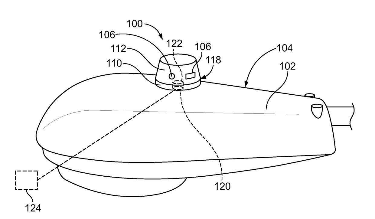
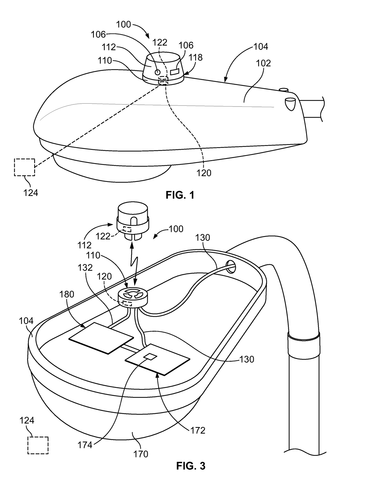
[0010]FIG. 1 illustrates a light sensor assembly 100 formed in accordance with an exemplary embodiment. The light sensor assembly 100 is mounted to a housing 102, such as a housing of a light fixture 104, such as a roadway light, a parking lot light, a street light, and the like, or to another component, such as the pole or other structure supporting the light fixture 104, or to another component unassociated with the light fixture, such as a parking meter, a telephone pole or another structure. The light sensor assembly 100 holds one or more sensors or photocontrol components 106 that is / are used to control the light fixture 104, such as for turning the light fixture on or off depending upon light levels, for dimming control of the light fixture, or for controlling other functions. The photocontrol components 106 may be used for other functions other than controlling the light fixture 104, such as remote monitoring of the environmental surroundings of the housing 102, such as for p...


PUM


Abstract

A light sensor assembly includes a photocontrol receptacle connector configured to be mounted to a housing, such as of a light fixture. The receptacle connector has a mating interface for mating with a photocontrol sensor connector. The receptacle connector holds contacts at the mating interface for electrical connection with corresponding contacts of the photocontrol sensor connector for controlling the light fixture. The contacts are configured to be electrically connected to power wires of the light fixture. The receptacle connector includes a receptacle connector communication device for wireless communication with the photocontrol sensor connector.

Description

BACKGROUND OF THE INVENTION[0001]The subject matter herein relates generally to outdoor lighting control.[0002]On outdoor lighting, notably street lights and parking lot lights, photocontrol components and the corresponding mating receptacles are typically used to turn the lights on and off based upon the ambient light from the sun. Some light fixtures support dimming to variably control the light fixture based on the ambient light levels, time of day. There is a trend to provide programmable functions to the light fixtures based on sensors and programmable controls other than ambient light, such as, detected nearby pedestrian motion. To accommodate these functions, the lighting control receptacles provide additional signaling contacts at the interface between the photocontrol component and the receptacle component mounted to the housing of the light fixture. However, the area available on the components for such signaling contacts is small due to standard arrangement of contacts su...

Claims


Application Information

Patent Timeline
IPC IPC(8): H05B37/02H01R13/66G01J1/42G01J1/44
CPCH05B37/0218H01R13/6683H01R13/6691G01J1/4204F21W2131/103H05B37/0227H05B37/0272F21S8/086G01J1/44F21V23/0442F21V23/045H05B47/11Y02B20/40H05B47/115H05B47/19H05B47/195
Inventor STUBY, JR., RICHARD G.
Owner TYCO ELECTRONICS LOGISTICS AG (CH)
Learn More