Gas resistant pothead system and method for electric submersible motors

a technology of electric submersible motors and potheads, which is applied in the direction of cable connections, coupling device connections, and accessories of boreholes/wells, etc., can solve the problems of affecting the insulating and sealing effect of affecting the insulating effect of the encapsulation, and exposing the downhole esp assembly

Active Publication Date: 2018-03-29
HALLIBURTON ENERGY SERVICES INC
View PDF7 Cites 6 Cited by
  • Summary
  • Abstract
  • Description
  • Claims
  • Application Information

AI Technical Summary

Benefits of technology

[0008]One or more embodiments of the invention enable a gas resistant pothead system and method for electric submersible motors.

Problems solved by technology

A problem that arises is that, the downhole ESP assembly may be exposed to gas that damages the encapsulation, elastomeric and sealing components of the pothead.
The gas causes the insulating and sealing elements of the conventional pothead to decompress and delaminate, causing a loss of their insulating and sealing benefits.
For example, sour gas can cause a gas decompression event including loss of the pressure seal and delamination of the power cable insulation, which can lead to shorts in the MLE.
Once the gases are inside the pothead body, the gas penetrates and attacks the cable and motor conductors and can even contaminate the motor oil, leading to motor failure and shortening the operational lifetime of the pump.
Submersible motor components are especially difficult to repair or replace since the motor assembly is often located deep underground, sometimes thousands of feet deep.
The problem with using lead solder is that the lead solder melts at around 377° F., lower than the operating conditions experienced by the downhole ESP motor, which can be as high as 450° F. Higher temperature solders do not solve the problem because they cannot bond to the lead sheath of the cable, since the lead sheath itself melts and also terminates inside the pothead.
Use of lead solder also requires a skilled artist to manufacture the pothead, and even then, there is a high manufacturing defect rate.
As is apparent from the above, current electrical submersible motor pothead connections are not suitable for gaseous, high temperature downhole conditions experienced by ESP motors.

Method used


Image

  • Gas resistant pothead system and method for electric submersible motors
  • Gas resistant pothead system and method for electric submersible motors
  • Gas resistant pothead system and method for electric submersible motors

Examples


Embodiment Construction

[0024]A gas resistant pothead system and method for electric submersible motors is described. In the following exemplary description, numerous specific details are set forth in order to provide a more thorough understanding of embodiments of the invention. It will be apparent, however, to an artisan of ordinary skill that the present invention may be practiced without incorporating all aspects of the specific details described herein. In other instances, specific features, quantities, or measurements well known to those of ordinary skill in the art have not been described in detail so as not to obscure the invention. Readers should note that although examples of the invention are set forth herein, the claims, and the full scope of any equivalents, are what define the metes and bounds of the invention.

[0025]As used in this specification and the appended claims, the singular forms “a”, “an” and “the” include plural referents unless the context clearly dictates otherwise. Thus, for exa...


PUM

PropertyMeasurementUnit
temperatureaaaaaaaaaa
thickaaaaaaaaaa

Abstract

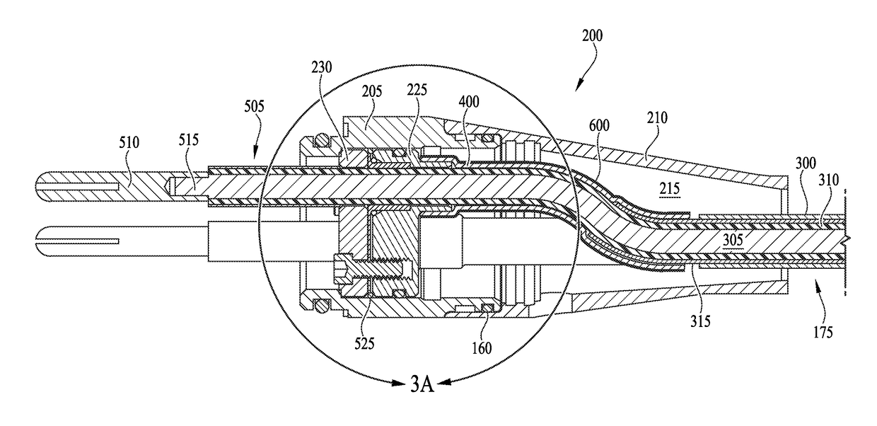
A gas resistant pothead system and method for electric submersible motors. A gas resistant pothead system includes a lead foil wrapped motor lead cable (MLE) extending through a pothead, a sleeve of an insulator block inside the pothead, the sleeve including gold plating and lead-foil wrapping over the gold plating, and a lead-to-gold seal formed between the gold plating of the sleeve and the lead foil wrapping over the gold plating. A method of creating a seal to gas around a power cable connection to a downhole electric submersible motor includes wrapping lead foil around a MLE extending through a pothead, continuing the lead foil wrapping around a gold-plated sleeve of an insulating block inside the pothead, mechanically reinforcing the lead foil with an encapsulant, and bonding the lead foil to the gold plating of the insulating block.

Description

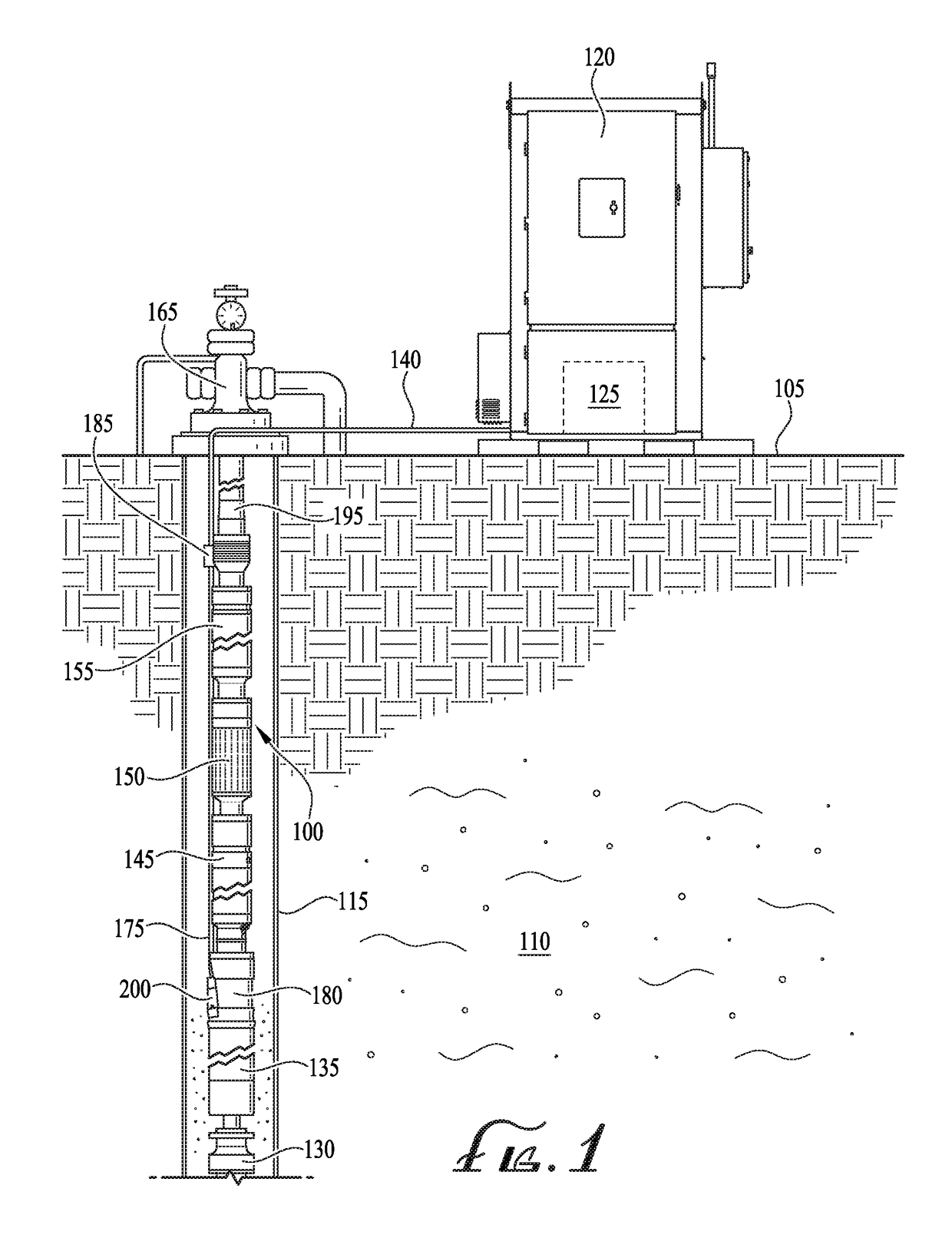
CROSS REFERENCE TO RELATED APPLICATIONS[0001]This application claims the benefit of U.S. Provisional Application No. 62 / 400,204 to Frey et al., filed Sep. 27, 2016 and entitled “ELECTRIC SUBMERSIBLE MOTOR POTHEAD SYSTEM AND APPARATUS,” which is hereby incorporated by reference in its entirety.BACKGROUND OF THE INVENTION1. Field of the Invention[0002]Embodiments of the invention described herein pertain to the field of electric submersible motor power cable connections. More particularly, but not by way of limitation, one or more embodiments of the invention enable a gas resistant pothead system and method for electric submersible motors.2. Description of the Related Art[0003]Fluid, such as natural gas, oil or water, is often located in underground formations. When pressure within the well is not enough to force fluid out of the well, the fluid must be pumped to the surface so that it can be collected, separated, refined, distributed and / or sold. Centrifugal pumps are typically used ...

Claims


Application Information

Patent Timeline
Patent Type & Authority Applications(United States)
IPC IPC(8): H01R13/523H01B7/28H01B7/04H01R13/52H01R43/00
CPCH01R13/523H01B7/2813H01B7/046H01R13/5221H01R43/005E21B43/128E21B17/028H01R13/5205E21B17/0285
Inventor FREY, JEFFREY G.GLASSCOCK, TERRY L.DAVIS, GREGORY AUSTIN
Owner HALLIBURTON ENERGY SERVICES INC
Why Eureka
Try Eureka