
Liquid crystal display device

a technology of liquid crystal display and liquid crystal molecules, which is applied in the direction of semiconductor devices, instruments, optics, etc., can solve the problems of inability to correct misalignment of liquid crystal molecules

Active Publication Date: 2018-03-29
SAMSUNG DISPLAY CO LTD
View PDF2 Cites 4 Cited by
  • Summary
  • Abstract
  • Description
  • Claims
  • Application Information

AI Technical Summary

Benefits of technology

The invention is a liquid crystal display (LCD) device that addresses a conflict in control over liquid crystal molecules caused by a light-shielding member and a protrusion pattern. The device includes a first display substrate with a pixel electrode and a protrusion pattern, a second display substrate facing the first display substrate, and a liquid crystal layer interposed between the substrates. The second display substrate includes a light-shielding member with indentation pattern parts that overlap with parts of the pixel electrode. The device is capable of improving the alignment of misaligned liquid crystal molecules and ensuring better control over the liquid crystal molecules.

Problems solved by technology

In a case in which a control force for liquid crystal molecules, generated by a light-generating member, and a control force for the liquid crystal molecules, generated by a protrusion pattern, are opposite to each other, the liquid crystal molecules may be misaligned because of insufficient control over the liquid crystal molecules.
Especially in a case in which the liquid crystal molecules are misaligned by external pressure because of an insufficient control force for the liquid crystal molecules, it may not be able to correct the misaligned liquid crystal molecules.

Method used


Image

  • Liquid crystal display device
  • Liquid crystal display device
  • Liquid crystal display device

Examples


Embodiment Construction

[0024]The invention will now be described more fully hereinafter with reference to the accompanying drawings, in which preferred embodiments of the invention are shown. This invention may, however, be embodied in different forms and should not be construed as limited to the embodiments set forth herein. Rather, these embodiments are provided so that this disclosure will be thorough and complete, and will filly convey the scope of the invention to those skilled in the art. The same reference numbers indicate the same components throughout the specification. In the attached figures, the thickness of layers and regions is exaggerated for clarity.

[0025]It will be understood that, although the terms first, second, third, etc., may be used herein to describe various elements, these elements should not be limited by these terms. These terms are only used to distinguish one element from another element. Thus, a first element discussed below could be termed a second element without departing...


PUM

PropertyMeasurementUnit
shapeaaaaaaaaaa
semi-elliptical shapeaaaaaaaaaa
electric fieldaaaaaaaaaa

Abstract

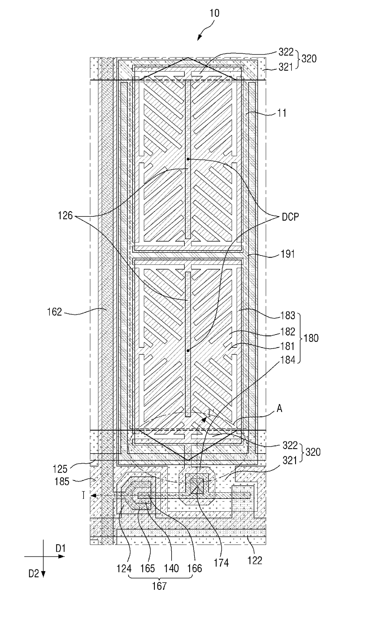
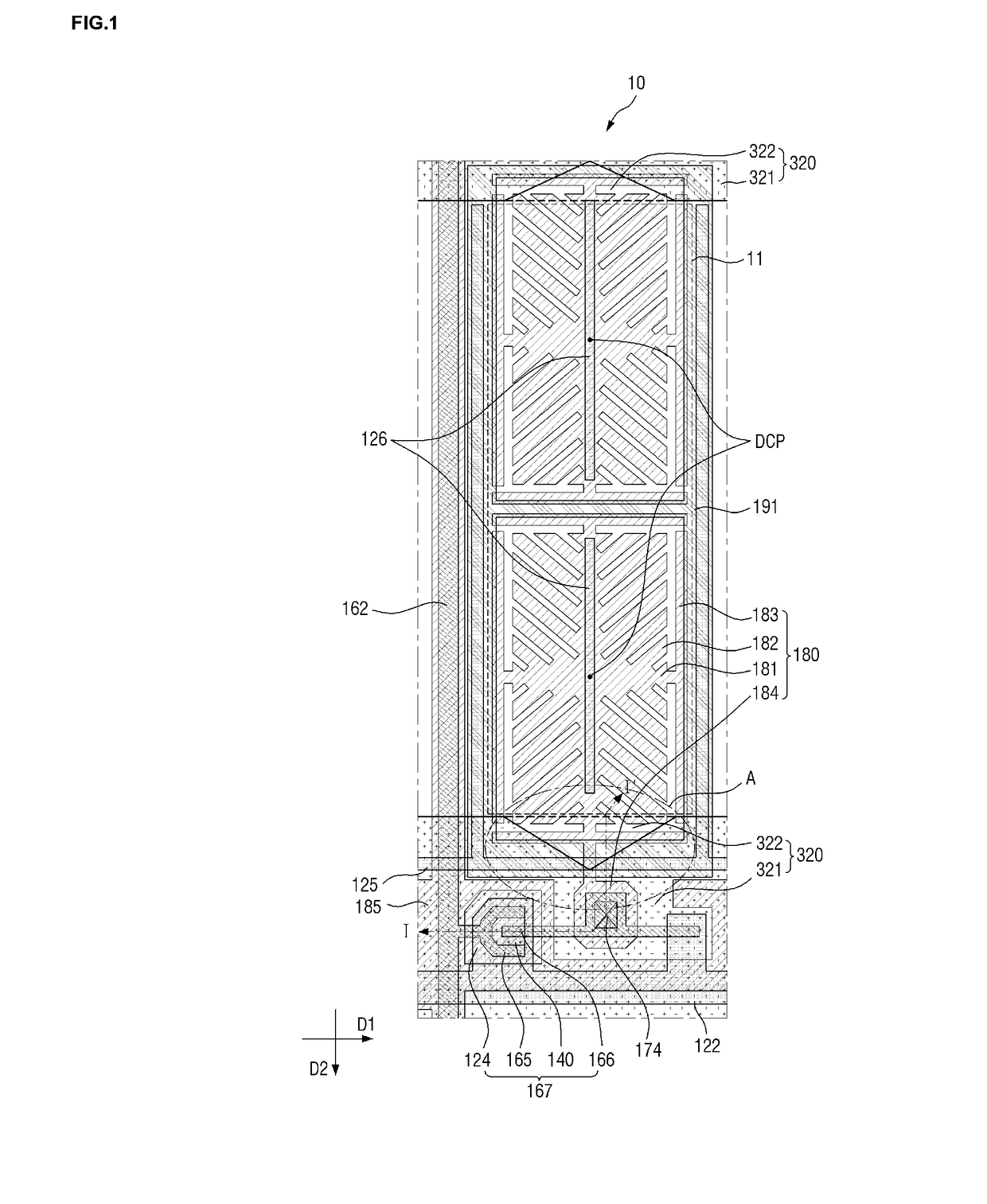
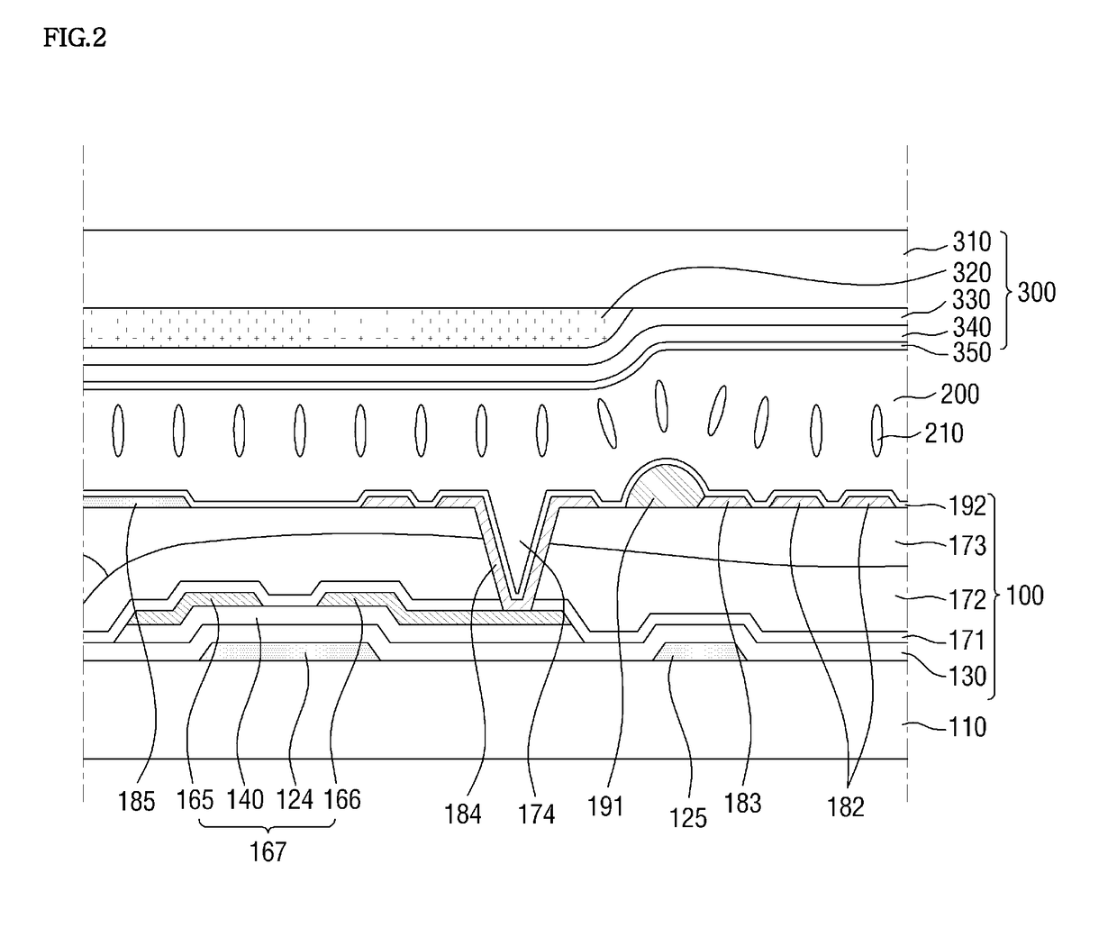
A liquid crystal display includes a first display substrate, a second display substrate facing the first display substrate, and a liquid crystal layer interposed between the first and second display substrates, where the first display substrate includes a lower substrate, a pixel electrode, which is disposed on the lower substrate, and a protrusion pattern, which is disposed on the pixel electrode along an outer edge of the pixel electrode, the second display substrate includes an upper substrate and a light-shielding member, which is disposed on a surface of the upper substrate facing the first display substrate and in which indentation pattern parts are inwardly indented in a plan view, the light-shielding member includes light-shielding parts that are an entirety of the light-shielding member except for the indentation pattern parts, and the indentation pattern parts overlap parts of the pixel electrode.

Description

[0001]This application claims priority to Korean Patent Application No. 10-2016-0122106, filed on Sep. 23, 2016, and all the benefits accruing therefrom under 35 U.S.C. § 119, the content of which in its entirety is herein incorporated by reference.BACKGROUND1. Field[0002]Exemplary embodiments of the invention relate to a liquid crystal display (“LCD”) device.2. Description of the Related Art[0003]A liquid crystal display (“LCD”) device, which is one of the most widely-used display devices, generally includes two substrates on which field-generating electrodes such as pixel electrodes and a common electrode are formed, respectively, and a liquid crystal layer which is inserted between the two substrates. The LCD device generates an electric field in the liquid crystal layer by applying voltages to the field-generating electrodes, respectively, and displays an image by determining an orientation of liquid crystal molecules in the liquid crystal layer and controlling a polarization of...

Claims


Application Information

Patent Timeline
Patent Type & Authority Applications(United States)
IPC IPC(8): G02F1/1335H01L51/00H10K99/00
CPCG02F1/133528G02F1/133509G02F1/133707G02F2001/1635H01L51/0024G02F1/133512G02F1/1343G02F1/134309G02F1/136286G02F1/1368G02F2201/123H10K71/50
Inventor LEE, SEUNG KYUNAM, GUNG WANSOHN, WOO SUNGJO, MI HYEONHONG, KI PYO
Owner SAMSUNG DISPLAY CO LTD
Learn More