Method for producing forged crankshaft

a crankshaft and crankshaft technology, applied in the direction of crankshafts, engine components, metal-working apparatus, etc., can solve the problems of difficult to produce such a forged crankshaft, difficult to remove the formed forged blank from the die, and prolong the life of the pin, so as to achieve simple process, reduce weight, and ensure stiffness

Active Publication Date: 2018-03-22
NIPPON STEEL CORP
View PDF0 Cites 0 Cited by
  • Summary
  • Abstract
  • Description
  • Claims
  • Application Information

AI Technical Summary

Benefits of technology

[0044]In a forged crankshaft production method according to the present invention, in a die forging step, a forged blank is formed to include first excess portions attached to some or all of the crank arms each incorporating a counterweight, each of the first excess portions protruding from a side portion of the crank arm which the first excess portion is attached to, in a region near the journal adjacent to the crank arm. In a pressing step, the first excess portions are deformed such that each of the first excess portions bulges toward the pin adjacent to the crank arm which the first excess portion is attached to, whereby the side portion of the arm in a region near the journal adjacent to the crank arm is thickened. In this way, stiffness can be ensured efficiently as compared with a case of simply forming a recess, while a recess formed inside of the side portion allows for a reduction in weight. This production method does not require the use of a punch, and therefore, this production method can be carried out in a simple process without requiring any great force.

Problems solved by technology

According to Patent Literature 2, because of the thin portion, the arm bends when a reciprocating motion of a piston puts a load on the pin, and therefore, the stress is dispersed, thereby lengthening the life of the pin.
It is, however, difficult to produce such a forged crankshaft with such arms having a unique shape by a conventional production method.
When a recess is to be formed in the surface of an arm in the die forging step, the draft of the die will become a reverse draft at the site of the recess, and therefore the formed forged blank will not be able to be removed from the die.

Method used


Image

  • Method for producing forged crankshaft
  • Method for producing forged crankshaft
  • Method for producing forged crankshaft

Examples


Embodiment Construction

[0094]A forged crankshaft producing method according to an embodiment will hereinafter be described with reference to the drawings.

1. Shape of Crankshaft

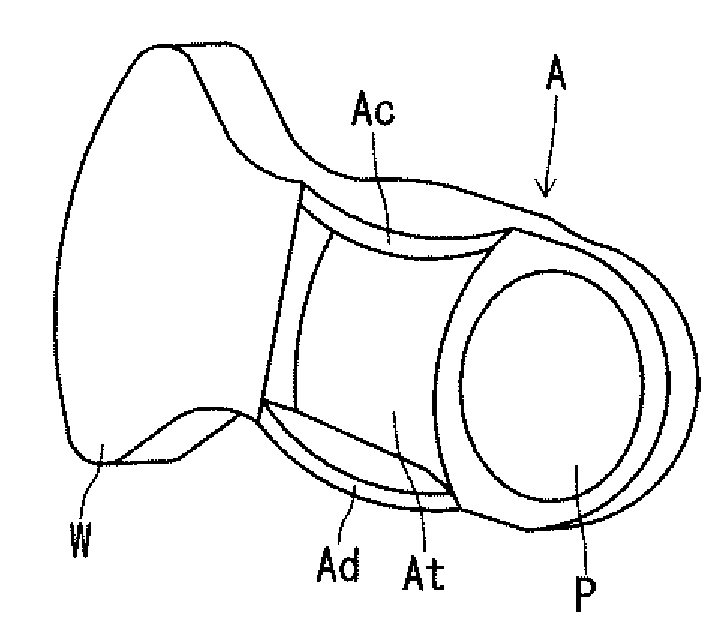
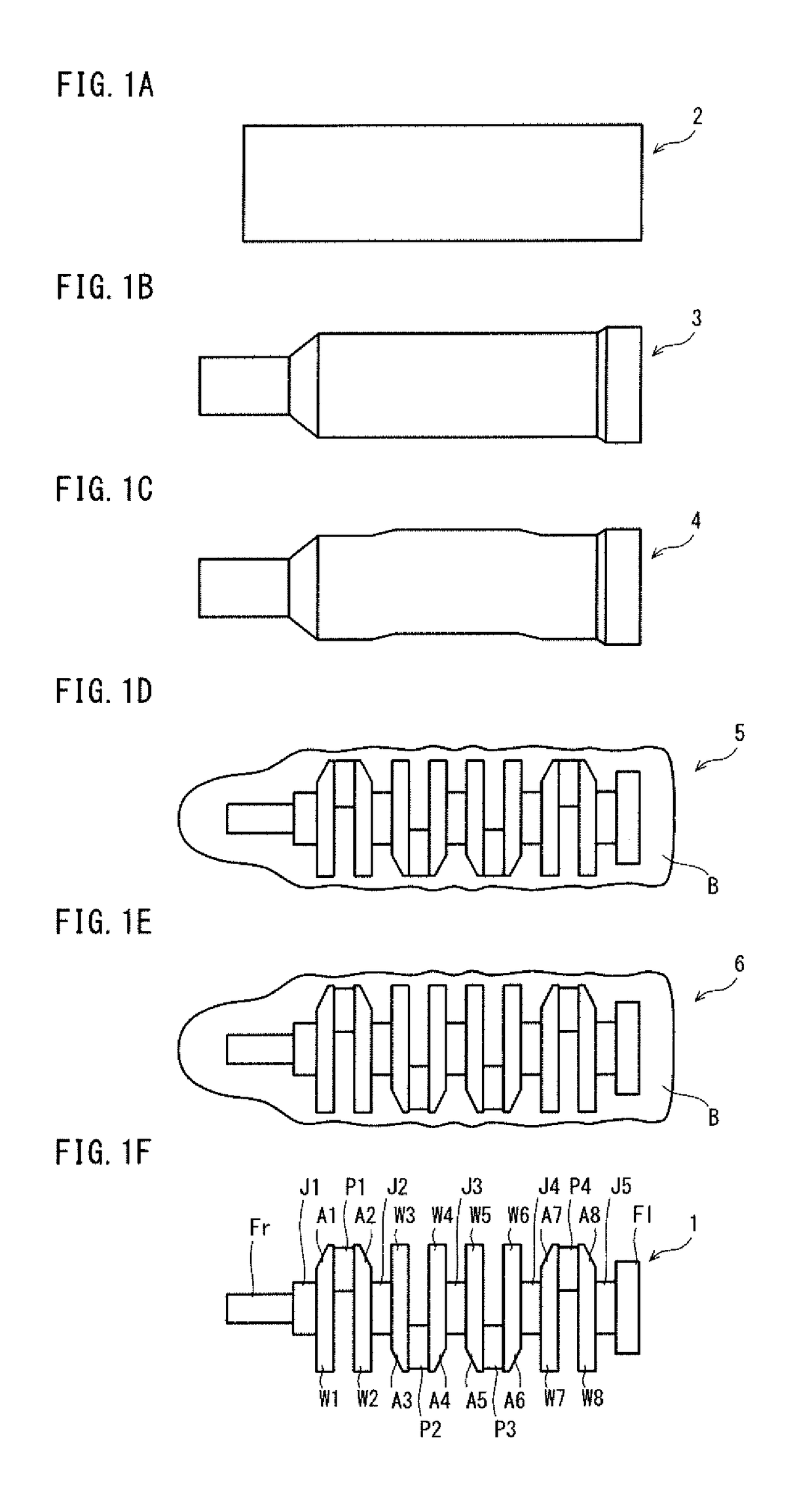
[0095]A forged crankshaft that is the target of the present embodiment includes journals serving as a center of rotation, pins decentered from the journals, arms each connecting one of the journals and one of the pins adjacent thereto, and weights integrated with some or all of the arms respectively. Such a crankshaft is, for example, a forged crankshaft as shown by FIGS. 2A to 4B.

[0096]FIGS. 2A to 2D are schematic diagrams showing an example of the shape of a pin-facing surface of an arm of a crankshaft produced by a production method according to the present invention. FIG. 2A is a perspective view, FIG. 2B is a view showing the pin-facing surface, FIG. 2C is a view showing a side surface, and FIG. 2D is a sectional view along the line IID-IID. FIGS. 2A to 2D show one of the arms of the crankshaft, the arm incorporating a weight. ...


PUM

PropertyMeasurementUnit
inclination anglesaaaaaaaaaa

Abstract

A method for producing a forged crankshaft includes a die forging step of forming a forged blank having a crankshaft shape by die forging, and a pressing step of pressing the forged blank by a first dies. The forged blank includes first excess portions attached to some or all of crank arms each incorporating a counterweight, each of the first excess portions protrudes from a side portion of the crank arm, in a region near a journal. In the pressing step, the first excess portions are deformed by the first dies such that each of the first excess portions bulges toward a pin. This facilitates the production of a forged crankshaft with a reduced weight and assured stiffness.

Description

TECHNICAL FIELD[0001]The present invention relates to a method for producing a crankshaft by hot forging.BACKGROUND ART[0002]A reciprocating engine to be employed in a motor vehicle, a motorcycle, an agricultural machine, a marine vessel or the like requires a crankshaft to extract power by converting reciprocating motions of pistons to rotational motion. There are two types of crankshafts: the type manufactured by die forging and the type manufactured by casting. Especially when high strength and high stiffness are required, die forged crankshafts (which will hereinafter be referred to as forged crankshafts) are often employed.[0003]A forged crankshaft is generally produced by using a billet as a starting material. The billet has a circular or square cross section, and the cross sectional area is constant throughout the length. A method for producing a forged crankshaft includes a preforming step, a die forging step, and a trimming step. After the trimming step, a coining step may ...

Claims


Application Information

Patent Timeline
Patent Type & Authority Applications(United States)
IPC IPC(8): B21J5/02F16C3/08B21K1/08
CPCB21J5/02F16C3/08B21K1/08
Inventor TAMURA, KENJIOKUBO, JUNICHYOSHINO, KENYABUNO, KUNIHIROKUROKAWA, HIROYUKIYAMASHITA, TOMOHISATAKAMOTO, SHOISHIHARA, KOICHIRO
Owner NIPPON STEEL CORP
Why Eureka
Try Eureka