
Electronic Bilge Pump Switch with Monitoring and RF Communication, Apparatus and System

a technology of electronic bilge pump and switch, which is applied in the direction of machine-to-machine/machine-type communication service, wireless commuication service, instruments, etc., can solve the problems of affecting the operation of the pump, the life of the mechanical switch is relatively short, and the damage to the vessel can be extrem

Inactive Publication Date: 2018-03-15
VON MUELLER CLAY WERNER
View PDF6 Cites 5 Cited by
  • Summary
  • Abstract
  • Description
  • Claims
  • Application Information

AI Technical Summary

Benefits of technology

The patent describes a replacement for a mechanical switch used in a hypothermia alarm system. The replacement switch is an electronic device that controls the voltage and current passing through it, eliminating the need for additional wiring and ensuring proper connection. The electronic switch can also be used in conjunction with the existing mechanical switch to monitor its operation and prevent false pump operation.

Problems solved by technology

Bilge pumps must be activated before the accumulating liquids reach an excessive level, causing damage to or sinking the vessel.
However, bilge debris and other contamination built up over time and / or caused corrosion to prevent the mechanical components from moving as intended.
Additionally, these mechanical switches had relatively short lives compared to the boats in which they were installed and required replacement.
If shore power is lost or the sump switch malfunctions and the problem is not detected, the damage caused to the vessel can be extreme.
If water reaches the floor board of the saloon in a yacht, from the exterior the problem can go unnoticed while the damage to the engines can be tens of thousands of dollars.
These electronic switches must be calibrated during the manufacturing process and are susceptible to operational errors, including loss of calibration and false negative and false positive detection of liquid level, which can cause the pump to stay on continuously damaging the pump or, not starting the pump when the desired water activation level is reached.
While these attempts may have been somewhat successful in reducing false alarms and missed detections, they are either not completely successful or relatively expensive devices, or requiring additional wiring to be added to supply voltage to operate the electronic switch.

Method used


Image

  • Electronic Bilge Pump Switch with Monitoring and RF Communication, Apparatus and System
  • Electronic Bilge Pump Switch with Monitoring and RF Communication, Apparatus and System
  • Electronic Bilge Pump Switch with Monitoring and RF Communication, Apparatus and System

Examples


Embodiment Construction

[0034]It will be apparent to those skilled in the art, that is, to those who have knowledge or experience in this area of technology, that many uses and design variations are possible for the improved bilge pump switches disclosed herein. The following detailed discussion of various alternative and preferred embodiments will illustrate the general principles of the invention. Other embodiments suitable for other applications will be apparent to those skilled in the art given the benefit of this disclosure.

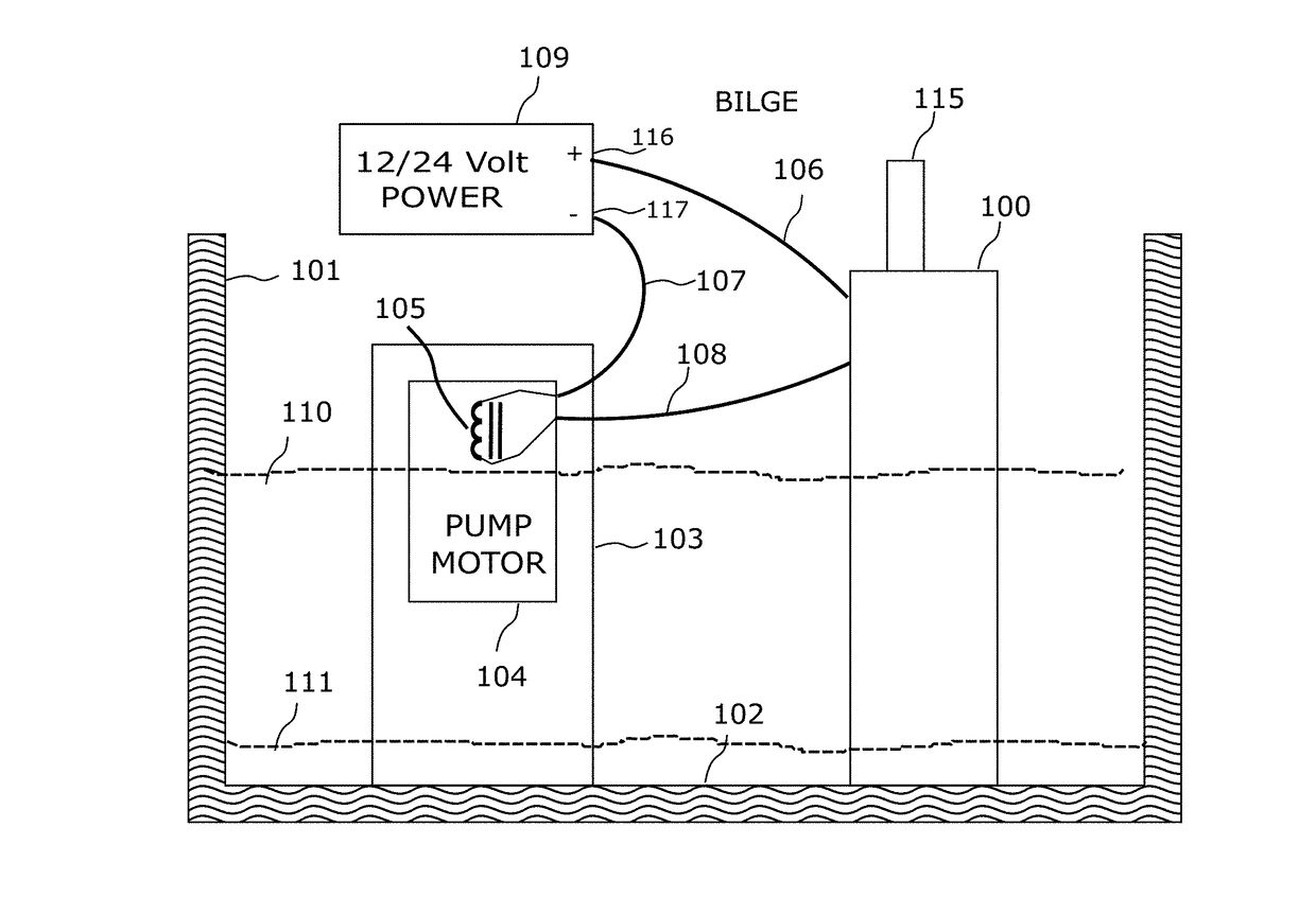
[0035]Referring now to the drawings, FIGS. 1 to 9 illustrate a bilge pump switch 100 according to the present invention. The illustrated bilge switch 100 is mounted at the bottom of a bilge in a boat 101 and is electrically connected to a 12 volt power source 109, and a bilge pump 103 in order to selectively energize the pump and evacuate the water 110 and other bilge fluids in the bilge 102 of the boat 101. As best shown in FIGS. 2-4, the illustrated bilge pump switch 100 includes...


PUM


Abstract

An electronic controller for a bilge pump providing the functions of monitoring liquid level in a boat bilge, and controlling the operation of the bilge pump, and monitoring the bilge pump operation, including bilge temperature, the bilge pump current and voltage, and maintaining a log of the collected data and providing the data to a remote device. In addition, the pump controller dynamically adjusts the bilge pumps operation based on commands received from a remote device and the logged data. In addition, the system monitors for hazardous materials within the bilge fluid preventing discharge within protected water ways.

Description

CROSS-REFERENCE TO RELATED APPLICATIONS[0001]Not ApplicableSTATEMENT REGARDING FEDERALLY SPONSORED RESEARCH[0002]Not ApplicablePARTIES TO A JOINT RESEARCH AGREEMENT[0003]Not ApplicableREFERENCE TO APPENDIX[0004]Not ApplicableFIELD OF THE INVENTION[0005]The field of the present invention generally relates to sensors for detecting the presence of fluids for activating a pump, and more specifically, to fluid sensors mounted in boat bilge tanks for activating a bilge pump when bilge fluid reaches a preset level above the bottom of the bilge tank, logging operational data and sending informational data along with alerts and statistical data to remote devices.BACKGROUND OF THE INVENTION[0006]All boats or ships accumulate liquids, including mostly water, in there bilge area. Bilge pumps must be activated before the accumulating liquids reach an excessive level, causing damage to or sinking the vessel. Early bilge pumps were activated manually or by mechanical switches such as those that ha...

Claims


Application Information

Patent Timeline
Patent Type & Authority Applications(United States)
IPC IPC(8): B63B13/00H04L29/08H04W4/00G05D9/00
CPCB63B13/00H04L67/025H04W4/38G05D9/00B63J2099/006H04W4/006F04B23/021F04B49/04F04B49/065F04B49/00
Inventor VON MUELLER, CLAY WERNER
Owner VON MUELLER CLAY WERNER
Learn More