
Brake-by-wire system

a technology of brake wires and wires, applied in the direction of brake systems, failure-safe aspects, braking components, etc., can solve the problems that conventional braking systems add a significant weight penalty to the vehicle itself, and achieve the effect of reducing the weight of the vehicl

Inactive Publication Date: 2018-03-01
GM GLOBAL TECH OPERATIONS LLC
View PDF2 Cites 6 Cited by
  • Summary
  • Abstract
  • Description
  • Claims
  • Application Information

AI Technical Summary

Benefits of technology

The patent describes a system that includes multiple controllers and a driver. These controllers receive braking signals and generate braking commands based on those signals. The driver performs a voting operation to determine which command to activate. This system can be used in a vehicle to automatically brake based on the driver's intent. The technical effect of this patent is to provide a reliable and safe way to control braking in vehicles.

Problems solved by technology

Conventional braking systems also add a significant weight penalty to the vehicle itself.

Method used


Image

  • Brake-by-wire system
  • Brake-by-wire system
  • Brake-by-wire system

Examples


Embodiment Construction

[0012]The following description is merely exemplary in nature and is not intended to limit the present disclosure, its application or uses. It should be understood that throughout the drawings, corresponding reference numerals indicate like or corresponding parts and features.

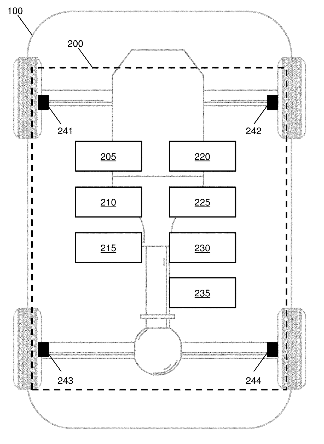
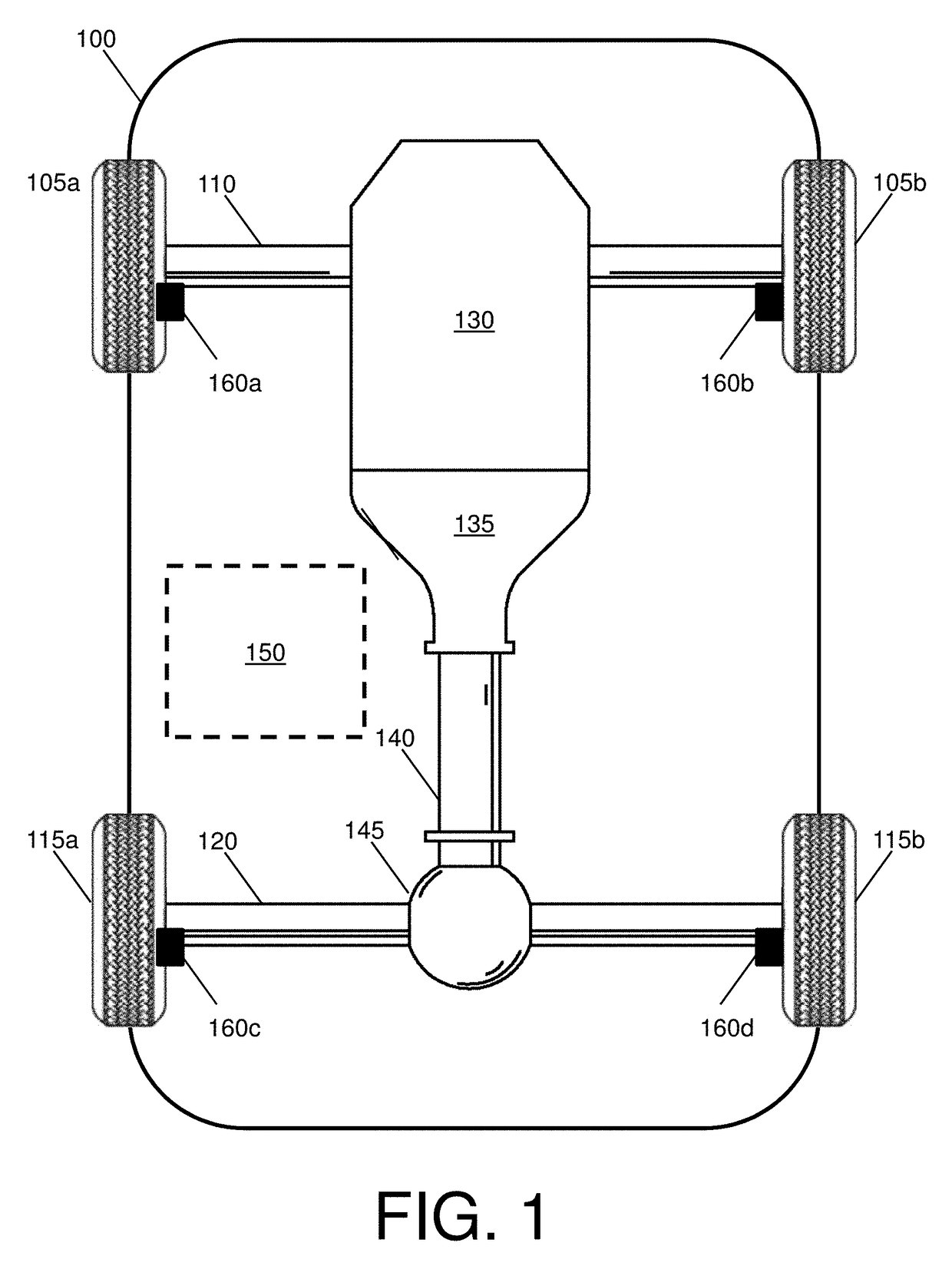
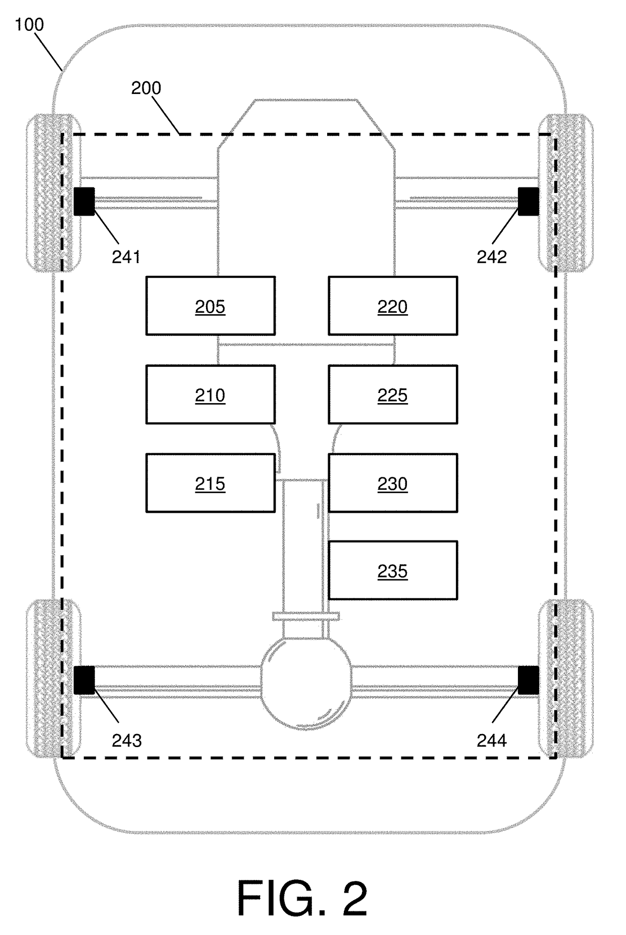
[0013]In accordance with an embodiment, FIG. 1 is a top schematic view of a vehicle 100. As illustrated in FIG. 1, the vehicle 100 includes a first wheel pair 105 (e.g., a wheel 105a and a wheel 105b), a first axle 110, a second wheel pair 115 (e.g., a wheel 115a and a wheel 115b), a second axle 120, an engine 130, a transmission 135, a driveshaft 140, a differential assembly 145, a brake-by-wire system 150, and a plurality of brake assemblies 160a-d.

[0014]The vehicle 100 may be any automobile, truck, van, sport utility vehicle, or the like. As used herein, the term vehicle is not limited to just an automobile, truck, van, or sport utility vehicle, but may also include any self-propelled or towed conveyance su...


PUM


Abstract

A vehicle is provided. The vehicle includes a plurality of controllers and a driver. Each controller is configured to receive one or more braking signals. Each controller is also configured to generate one or more braking commands in correspondence to the one or more braking signals. The driver is configured to perform a voting operation on the one or more braking commands to determine whether to generate a driving signal to at least one brake.

Description

FIELD OF THE INVENTION[0001]The invention disclosed herein relates to a vehicle having a brake-by-wire mechanism including a voting protocol for a fault tolerant operation.BACKGROUND[0002]Conventional braking systems that provide direct mechanical linkages and / or hydraulic force-transmitting-paths between an operator and brake control units of the vehicle. Conventional braking systems also add a significant weight penalty to the vehicle itself. Thus, reducing or replacing the conventional braking systems is desirable.[0003]Current industrial trends include reducing a number of overall mechanical components and an overall weight of the vehicle through system-by-wire applications, also referred to as X-by-wire systems. One such X-by-wire system is a brake-by-wire system, which sometimes referred to as an electronic braking system (EBS). Present implementations of brake-by-wire systems fail to include electrical redundancy vs mechanical redundancy (e.g., duplication of hardware and / or ...

Claims


Application Information

Patent Timeline
Patent Type & Authority Applications(United States)
IPC IPC(8): B60T13/74
CPCB60T13/741B60T2270/402B60T2270/82B60T2270/414B60T2270/404B60T13/74B60T7/042B60T7/22B60T13/662B60T2201/022B60T2201/03B60T2270/40
Inventor KRUEGER, ERIC E.HOUTMAN, ALAN J.WEBER, STEVEN J.
Owner GM GLOBAL TECH OPERATIONS LLC
Learn More