
An Extendible Tripod Leg

a tripod leg and leg extension technology, applied in the direction of rod connections, stands/trestles, fastening means, etc., can solve the problems of difficult to carry, difficult to carry, and high manufacturing cost of the tripod, and achieve the effect of lengthening or shortening the leg

Active Publication Date: 2018-02-22
VITEC GRP PLC
View PDF7 Cites 1 Cited by
  • Summary
  • Abstract
  • Description
  • Claims
  • Application Information

AI Technical Summary

Benefits of technology

The patent describes a device for clamping a leg brake in a bicycle. The device includes a cable that allows for relative movement between the actuating means and the leg brake, which makes the leg brake lighter and more robust. The use of cables also allows for the use of light and strong components, minimizing the need for adjustments of the locking mechanism. The device further includes a guide sleeve and a guide rail to stabilize the leg and prevent unwanted turning forces within the leg. Additionally, the device ensures simultaneous operation of both clamp assemblies and reduces the number of connections required. The inner cable of the Bowden cable is connected to the first clamp assembly and the outer sheath is connected to the second clamp assembly, which ensures equal force transmission between the actuating means and the clamp assemblies regardless of differences in position caused by assembly or wear.

Problems solved by technology

However, prior art mechanisms are relatively cumbersome and employ heavy mechanical linkages, such as torsion rods and / or push rods which detract from the ease of use of the tripod and also makes the tripod more expensive to manufacture and difficult to carry.

Method used


Image

  • An Extendible Tripod Leg
  • An Extendible Tripod Leg
  • An Extendible Tripod Leg

Examples


Embodiment Construction

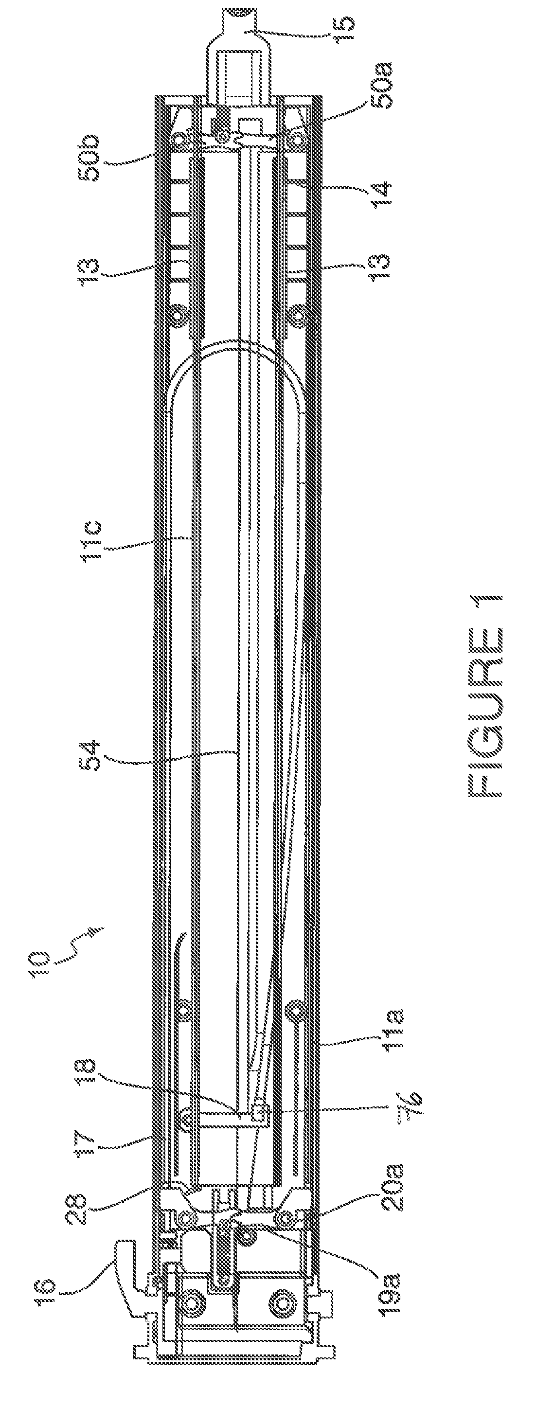
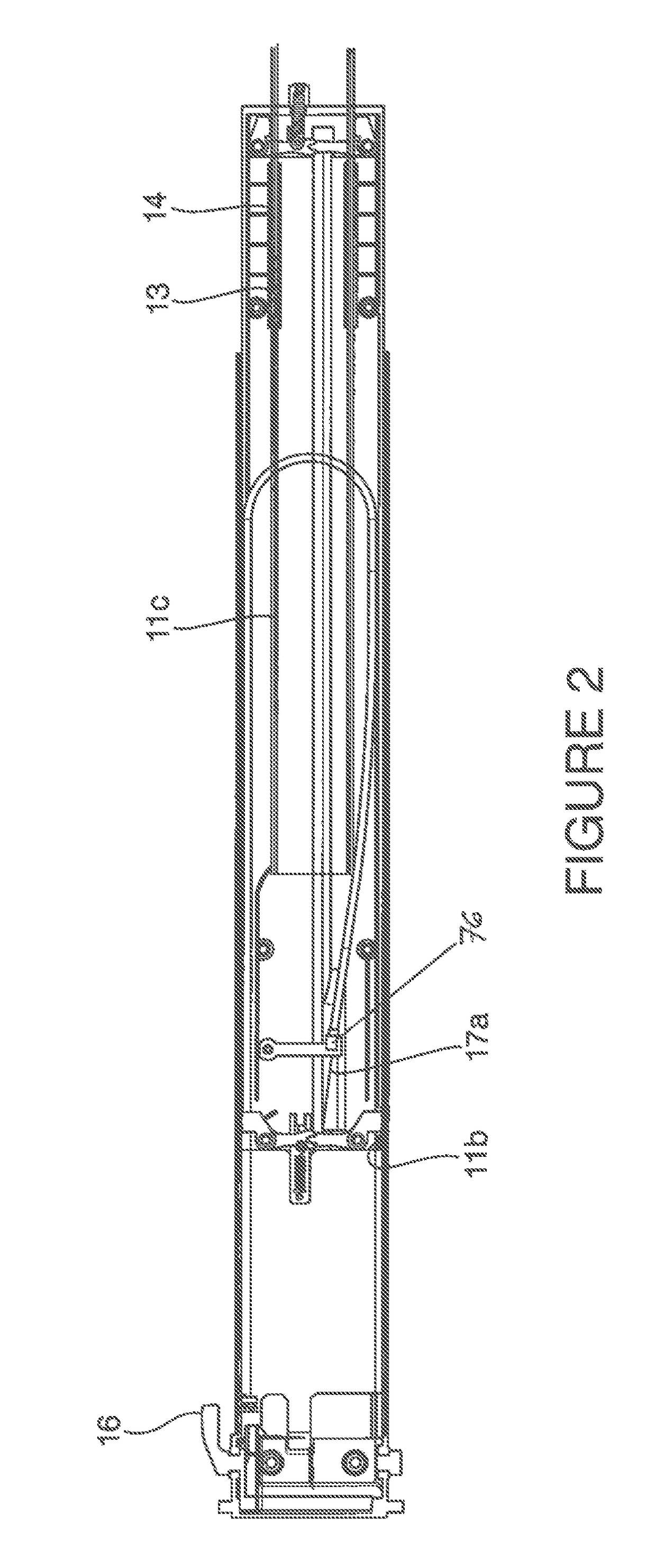
[0037]Referring initially to FIG. 1, this illustrates a first embodiment of a tripod leg, generally referenced 10. The leg 10 illustrated has three leg-stages which can move telescopically relative to each other, with a locking arrangement for the movement being controlled through a handle which can be simply operated by a user using only one hand. The leg, when incorporated into a tripod therefore enables said user to use their free hand to, for example, control the device being supported by the tripod. It should be appreciated that a leg can have further telescopic leg-stages without departing from the scope of the invention.

[0038]It is important that the locking arrangement be capable of supporting the mass of the device with no risk of slippage and also to withstand the torsion which can act on the legs of a tripod: particularly if the device or tripod is rotated.

[0039]In general, the tripod comprises two main elements: the head (or platform) and the legs. The head is mounted on...


PUM


Abstract

An extendable leg 10 for a tripod, the leg 10 comprises two or more leg-stages 11b, 11c, each leg-stage 11b, 11c moveable axially relative to one or more of the or each other leg-stages to lengthen or shorten the leg. The leg 10 includes a clamp assembly to releasably prevent the relative movement when the leg is at the desired length. The clamp assembly includes a leg brake 22a moveable between a first leg-stage locking position and a second leg-stage release position. In order to control movement of the leg brake 22a between the first and second positions, an actuation means 16 is provided. A cable 17 is operably connected at a first end to the actuation means 16 and at a second end to the leg brake 22a, such that operation of the actuation means 16 causes the cable 17 to move the leg brake 22a.

Description

FIELD OF THE INVENTION[0001]The present invention relates to an improved adjustable leg, primarily for use on a tripod designed to carry for example, a camera or other load. The leg is particularly suitable in allowing adjustment of the length of the tripod leg using only one hand.BACKGROUND TO THE INVENTION[0002]Tripods are well known for use where support needs to be provided, in a stable fashion, for devices such as cameras or theodolites whilst the device is in operation. The tripod firstly reduces the risk of movement of the device occurring during such operation and also leaves the operator free to carry out other tasks.[0003]A typical tripod comprises a platform mounted on legs with each leg being mounted at an equal distance from each of the other two legs.[0004]The platform can have attachment means for the device and other components and also electrical connections enabling the device to be operated remotely if required.[0005]Additionally, the length of a leg can be length...

Claims


Application Information

Patent Timeline
Patent Type & Authority Applications(United States)
IPC IPC(8): F16M11/36F16B7/14B25G1/04
CPCF16M11/36F16B7/1454B25G1/04F16B7/1463F16M11/32G03B17/561F16M2200/028F16M2200/025F16M11/38F16B7/10
Inventor TORBITT, JOLYONBRADY, JAMESGUEST, JAMES
Owner VITEC GRP PLC
Learn More