Radio frequency filter having cavity structure

Active Publication Date: 2018-02-15
KMW INC
View PDF0 Cites 1 Cited by
  • Summary
  • Abstract
  • Description
  • Claims
  • Application Information

AI Technical Summary

Benefits of technology

The present patent describes a radio frequency filter with a cavity structure that is compact and lightweight. The filter has a minimized mechanical form and size, making it stable and easy to fix and couple the resonant element within the cavity. It can be made in a simple and plain structure. Additionally, the miniaturized and lightweight filter is easy to install in a base station or other locations. Overall, the technical effect of the patent is to provide a highly efficient, compact, and easy-to-use radio frequency filter.

Problems solved by technology

However, the radio frequency filter having a cavity structure suffers from limitations in providing desired weight reduction and miniaturization because the filter needs to be structured for providing a housing typically with a resonance element installed and to basically have a coupling structure of the housing with a cover.

Method used


Image

  • Radio frequency filter having cavity structure
  • Radio frequency filter having cavity structure
  • Radio frequency filter having cavity structure

Examples


Embodiment Construction

[0018]Some embodiments of the present disclosure will now be described in detail with reference to the accompanying drawings.

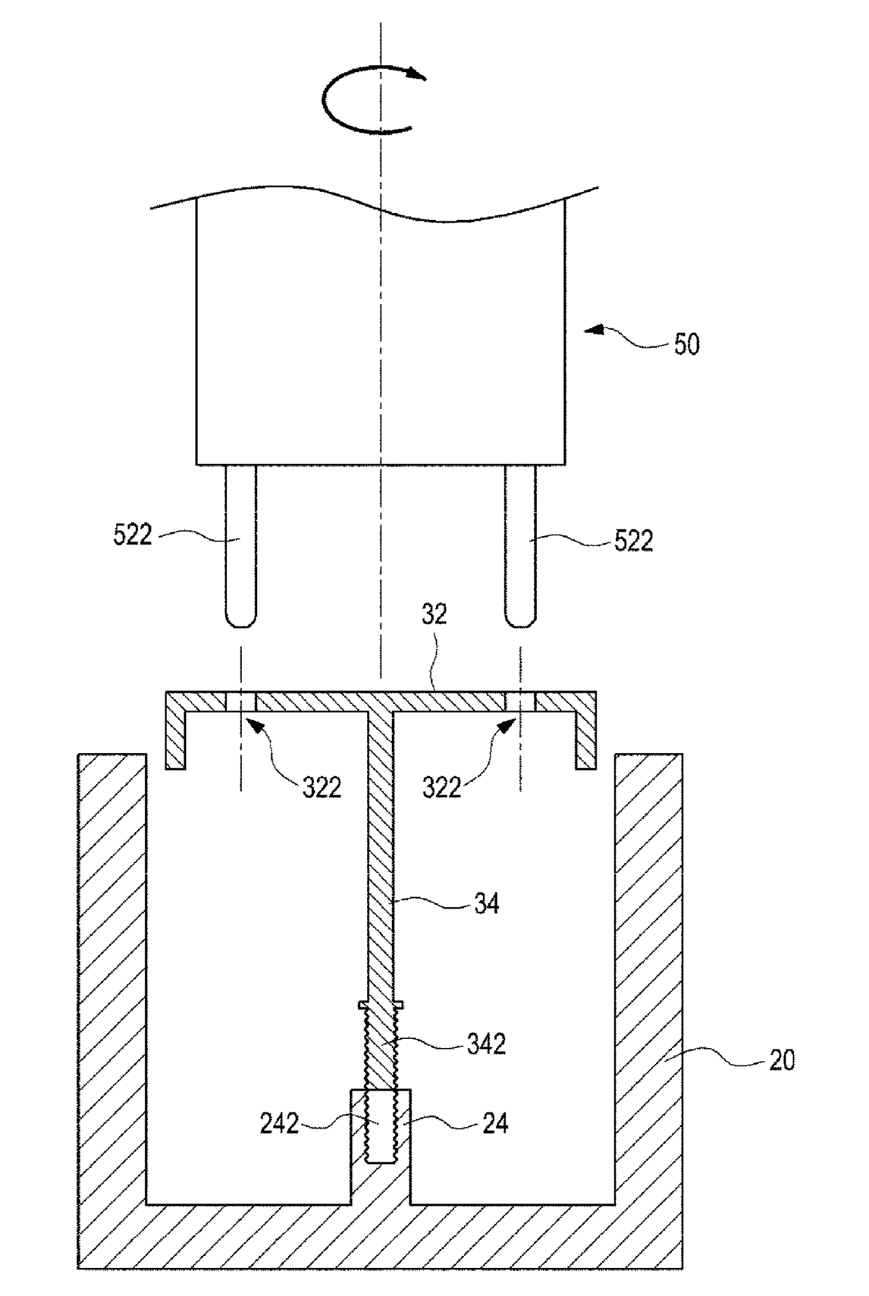
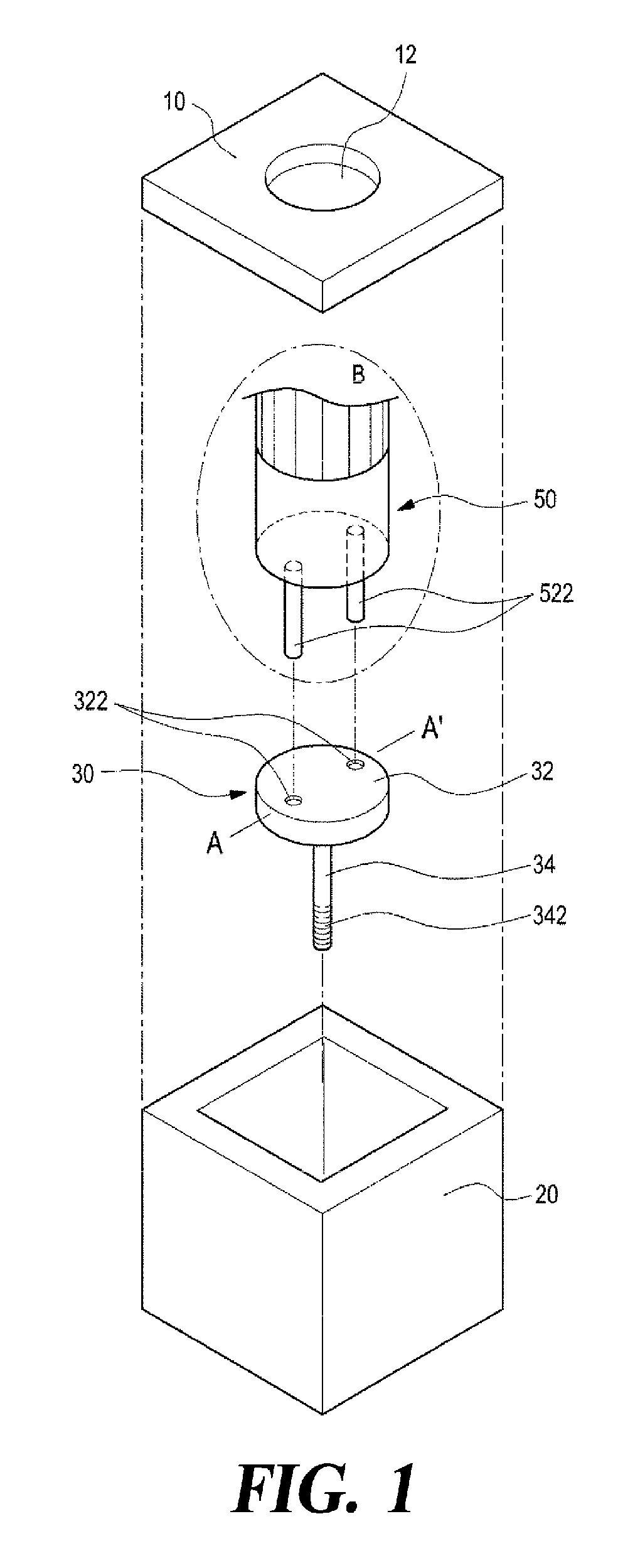
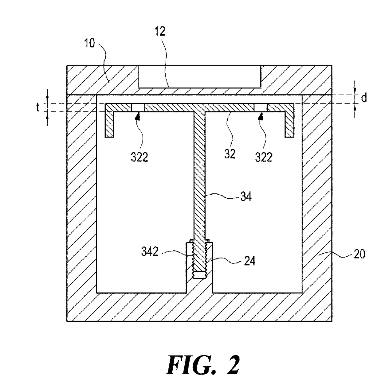
[0019]FIG. 1 is a partially exploded perspective view of a radio frequency filter having a cavity structure according to a first embodiment of the present disclosure, wherein the dot-dash circle shows an additional driver device 50 as a work tool for the installation work of a resonance element 30 for the sake of convenience of explanation. FIG. 2 is a sectional view taken along line A-A′ of the radio frequency filter in FIG. 1, which is completely assembled. FIG. 3 is a diagram illustrating the installation work performed on the resonance element in the radio frequency filter in FIG. 2 before its housing 20 is fitted with a cover 10 shown in FIG. 2.

[0020]Referring to FIGS. 1 to 3, the radio frequency filter having the cavity structure according to the first embodiment of the present disclosure, similar to prior art, is provided with an enclosure that has at l...


PUM


Abstract

The present disclosure provides a radio frequency filter having a cavity structure including a housing, a cover and a resonance element. The housing has a hollow interior for providing a cavity, and an open side. The cover shields the open side of the housing. The resonance element is positioned in the hollow interior of the housing, and has a planar portion and a support for supporting and fixing the planar portion to the housing. The planar portion of the resonance element has at least two through holes, and the support has a lower end portion formed with a male thread structure for screw fastening. The housing is formed with a female thread structure to be screw fastened with the male thread structure formed at the lower end portion of the support.

Description

TECHNICAL FIELD[0001]The present disclosure in some embodiments relates to a radio signal processing apparatus used in a radio communication system. More particularly, the present disclosure relates to a radio frequency filter having a cavity structure such as a cavity filter.BACKGROUND[0002]A radio frequency filter having a cavity structure generally utilizes a metallic housing for providing a plurality of accommodation spaces or cavities having a shape such as rectangular parallelepiped and the like, in which dielectric resonance elements (DR) or resonance elements having a metallic resonance rod are each provided for generating superhigh frequency resonance. Some radio frequency filters employ a structure that generates resonance by the shape of the cavity itself without using the dielectric resonance element. Further, a radio frequency filter having such a cavity structure is generally provided at its upper portion with a cover for shielding the open areas of the corresponding c...

Claims


Application Information

Patent Timeline
IPC IPC(8): H01P1/207H01P7/06
CPCH01P1/207H01P7/06H01P1/20H01P1/2053H01P7/04
Inventor PARK, NAM-SHINKIM, BYEONG-CHULJEONG, DAE-SOO
Owner KMW INC
Why Eureka
Try Eureka