Belt conveyor unit and image forming apparatus
- Summary
- Abstract
- Description
- Claims
- Application Information
AI Technical Summary
Benefits of technology
Problems solved by technology
Method used
Image

Examples
first exemplary embodiment
Architecture of Image Forming Apparatus
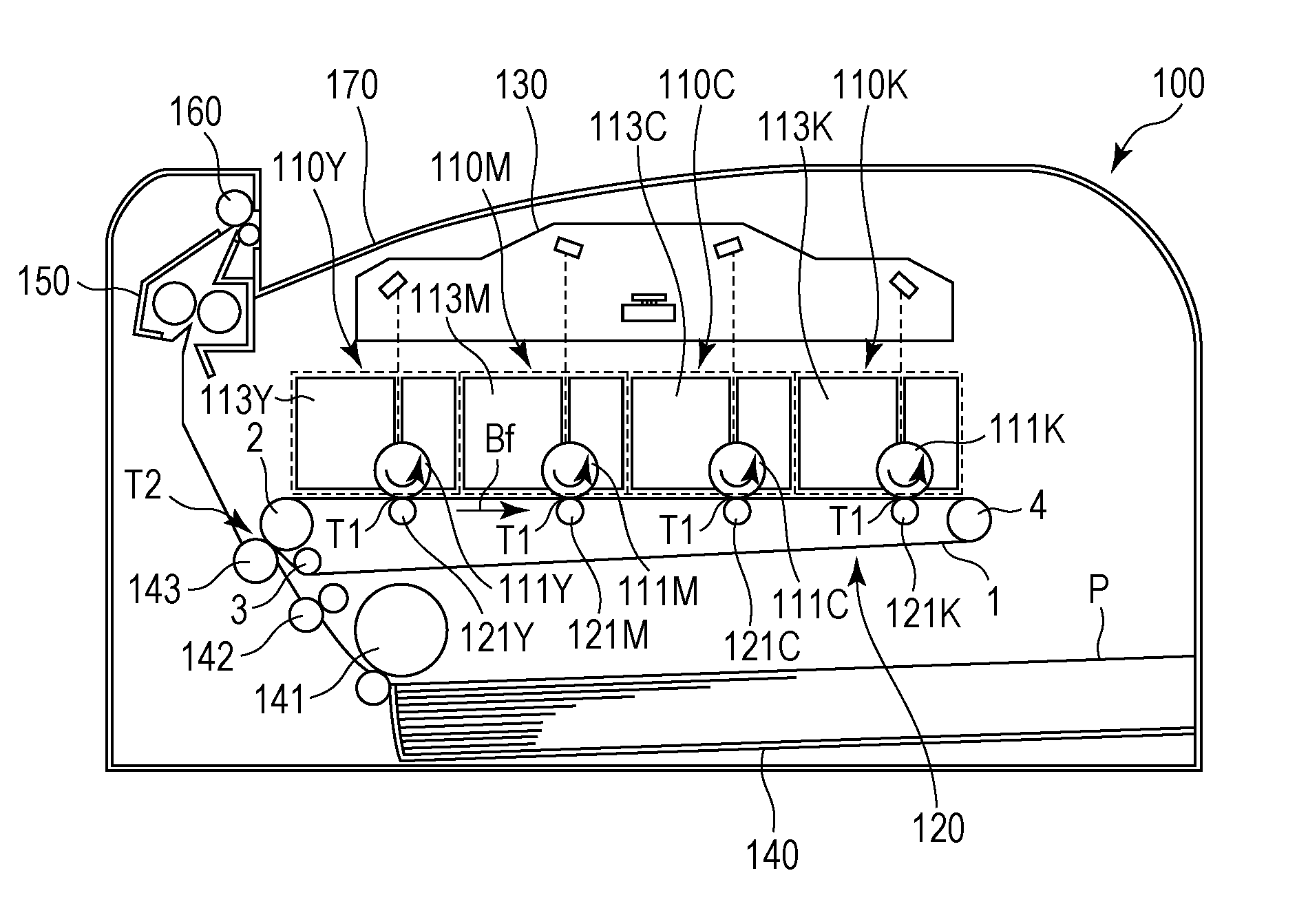
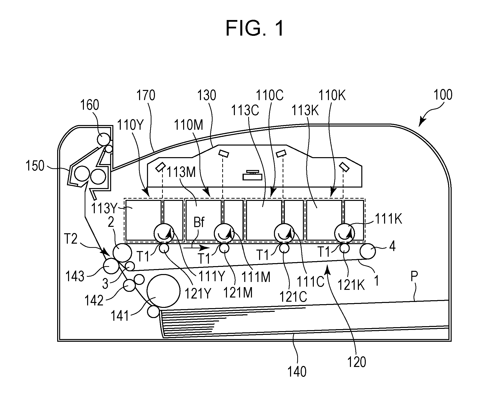
[0036]FIG. 1 is a schematic illustration of an example of a color image forming apparatus. The configuration of the image forming apparatus according to the present exemplary embodiment is described below with reference to FIG. 1. An image forming apparatus 100 can electrophotographically form an image on a transfer material P, such as a recording sheet or an OHP sheet, in accordance with a signal transmitted from an external device, such as a personal computer, connected thereto.
[0037]In the image forming apparatus 100, a plurality of image forming units 110Y, 110M, 110C, and 110K that form yellow, magenta, cyan, and black toner images, respectively, are arranged in a line in a substantially horizontal direction. In addition, a transfer unit that serves as a belt conveyor unit is disposed so as to face the image forming units 110Y, 110M, 110C, and 110K.
[0038]According to the present exemplary embodiment, the transfer unit is formed as an inter...
second exemplary embodiment
[0066]According to the first exemplary embodiment, the lateral shift of the belt is regulated by using the inclined flange rollers 14a and 14b that are rotatable independently from the tension roller 4. In contrast, according to the present exemplary embodiment, the inclined flange rollers 14a and 14b are rotatable in synchronization with the rotation of the tension roller 4. Note that since the other structures are similar to those of the image forming apparatus according to the first exemplary embodiment, the same numbering is used for similar components of the present exemplary embodiment in the following description.
[0067]FIG. 12A is a cross-sectional view of a tension roller 4 according to the second exemplary embodiment. By causing the inclined flange roller 14 of the first exemplary embodiment to rotate in synchronization with the rotation of the tension roller 4, the inclined flange roller 14 and the tension roller 4 are rotatable at the same angular velocity. FIG. 12B is an...
third exemplary embodiment
[0073]The first exemplary embodiment has been described with reference to regulation of the lateral shift of the belt 1 using the inclined flange rollers 14a and 14b that can rotate independently from the tension roller 4. In contrast, according to the present exemplary embodiment, a decrease in the durability of the belt 1 is reduced more than in the first exemplary embodiment by changing the shape of the inclined flange rollers 14a and 14b. Note that since the other structures are similar to those of the image forming apparatus according to the first exemplary embodiment, the same numbering is used for similar components of the present exemplary embodiment in the following description.
[0074]FIG. 13A is a cross-sectional view of a configuration in which an inclined flange roller 16 (16a, 16b) is employed instead of the inclined flange roller 14 (14a, 14b). FIG. 13B is an enlarged view of the left section of FIG. 13A. The inclined flange roller 16 has a roller surface 162 inclined a...
PUM
 Abstract
Description
Claims
Application Information
 - R&D
- Intellectual Property
- Life Sciences
- Materials
- Tech Scout
- Unparalleled Data Quality
- Higher Quality Content
- 60% Fewer Hallucinations
Browse by: Latest US Patents, China's latest patents, Technical Efficacy Thesaurus, Application Domain, Technology Topic, Popular Technical Reports.
© 2025 PatSnap. All rights reserved.Legal|Privacy policy|Modern Slavery Act Transparency Statement|Sitemap|About US| Contact US: help@patsnap.com