Display panel, electronic device and test method

a display panel and electronic device technology, applied in the field of display technologies, can solve the problems of not facilitating a narrow border design of the display panel, and achieve the effect of reducing the width of the border region, facilitating a narrow border design of the display panel, and ensuring the accuracy of testing

Active Publication Date: 2018-02-15
WUHAN TIANMA MICRO ELECTRONICS CO LTD
View PDF15 Cites 9 Cited by
  • Summary
  • Abstract
  • Description
  • Claims
  • Application Information

AI Technical Summary

Benefits of technology

[0011]It can be seen from the above description that, in the display panel, electronic device and test method according to the present disclosure, the test pins are electrically connected to the input ends via a portion of the data lines and provide the test signal via these data lines. The remaining data lines are electrically connected to the output ends. The data lines are reused as the signal lines for the test pins, instead of arranging the signal lines for the test pins in the border region, thereby reducing the width of the border region and facilitating a narrow border design of the display panel. The portion of the data lines are reused as the signal lines for the test pins to perform a display test on the pixel units in the display panel. This portion of the data lines can provide data lines for the pixel units connected to the portion of the data lines while providing the test signal to the pixel units connected to the remaining data lines. Since the luminance of the pixel units depend on stabilized voltages on all of the data lines, there is no difference between the luminance of the pixel units connected to the above portion of the data lines and the luminance of the pixel units connected to the remaining data lines, and the test accuracy may not be affected.

Problems solved by technology

In conventional display panels, a signal line for connecting the test pin with the test switching circuit needs to be arranged separately in the border region, so that the test signal can be provided to the test switching circuit via the test pin, which does not facilitate a narrow border design of the display panels.

Method used


Image

  • Display panel, electronic device and test method
  • Display panel, electronic device and test method
  • Display panel, electronic device and test method

Examples


Embodiment Construction

[0026]Hereinafter technical solutions in embodiments of the present disclosure are described clearly and completely in conjunction with the drawings. Apparently, the described embodiments are only a few rather than all of the embodiments of the present disclosure. Any other embodiments obtained by those skilled in the art based on the embodiments of the present disclosure without any creative effort fall within the scope of protection of the present disclosure.

[0027]Hereinafter, the technical solutions according to embodiments of the present disclosure are further described in details in conjunction with the drawings, hence the technical solutions become clearer.

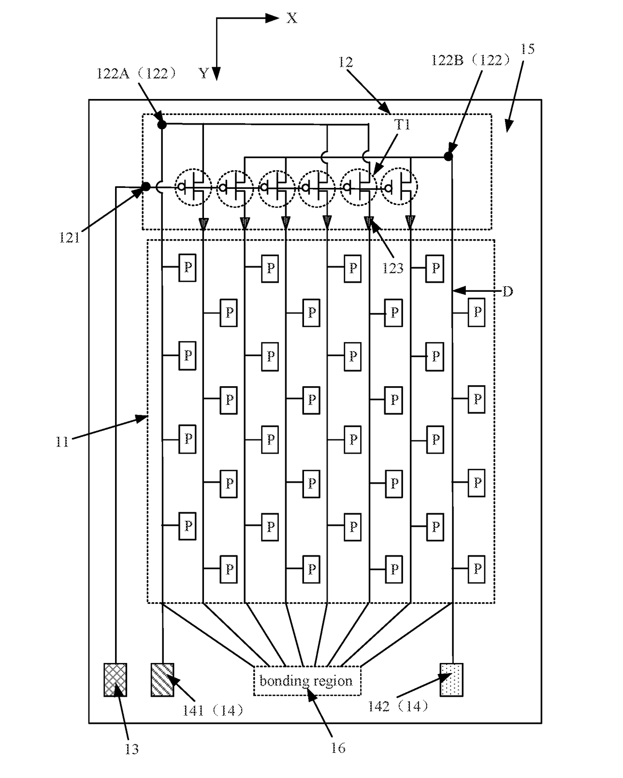
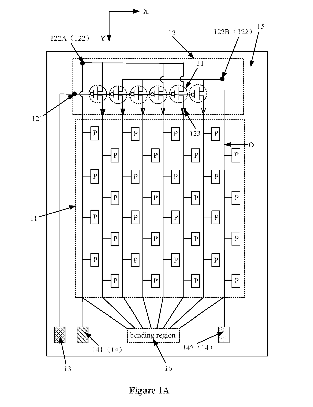
[0028]Reference is made to FIG. 1A, which is a schematic structural diagram of a display panel according to an embodiment of the present disclosure. The display panel includes multiple data lines D, a display array 11, a test switching circuit 12, a drive pin 13 and test pins 14. The data lines D are arranged in parallel and...


PUM

PropertyMeasurementUnit
colorsaaaaaaaaaa
coloraaaaaaaaaa
widthaaaaaaaaaa

Abstract

Provided are a display panel, an electronic device and a test method. The display panel includes: multiple data lines extending in a first direction; a display array including multiple pixel units arranged in an array, where the columns of the pixel units are electrically connected to the data lines respectively; a test switching circuit arranged at one side of the display array and test pins and a drive pin arranged at the other side of the display array in the first direction, where the test switching circuit includes a control end, input ends and output ends, the drive pin is connected to the control end, the test pins are configured to input a test signal and are connected to the input ends via a portion of the data lines, and the remaining data lines are connected to the output ends.

Description

PRIORITY CLAIM[0001]The present application claims the priority to Chinese Patent Application No. 201710270512.3, titled “DISPLAY PANEL, ELECTRONIC DEVICE AND TEST METHOD”, filed on Apr. 24, 2017 with the State Intellectual Property Office of the PRC, which is incorporated herein by reference in its entirety.FIELD[0002]The present disclosure relates to the field of display technologies, and in particular to a display panel, an electronic device and a test method.BACKGROUND[0003]With the continuous development of science and technologies, more and more electronic devices with display functions are widely applied in people's daily lives and work, greatly facilitate people's daily lives and work and become important and indispensable tools. A display panel is a main component for the display function of the electronic device. A liquid crystal display panel and an organic light emitting diode (OLED) display panel are two mainstream display panels in the conventional display art. Besides...

Claims


Application Information

Patent Timeline
Patent Type & Authority Applications(United States)
IPC IPC(8): H01L27/32G09G3/00G02F1/1362G02F1/13
CPCG06F3/0428G06F3/0414G02F1/1362G09G3/006G02F1/136254G02F1/1309G09G3/2092H10K59/131
Inventor ZHOU, JINGXIONGZHOU, RUIYUAN
Owner WUHAN TIANMA MICRO ELECTRONICS CO LTD
Why Eureka
Try Eureka