Latch assembly for a sliding door

a technology for latching doors and latches, which is applied in the direction of construction locks, construction fastening devices, building locks, etc., can solve the problems of insufficient rotation of latches about their vertical and horizontal axes, and inability of locksmiths to maintain a greater inventory,

Active Publication Date: 2018-02-08
ASSA ABLOY AUSTRALIA PTY LTD
View PDF8 Cites 7 Cited by
  • Summary
  • Abstract
  • Description
  • Claims
  • Application Information

AI Technical Summary

Benefits of technology

[0010]The latch assembly preferably includes an indicator visible from outside of the housing which interacts with the deadlatching member so as to visibly indicate if the deadlatching member is in a deadlatching, condition or if the lock mechanism is in an active condition. This provides the advantage of indicating to persons on the inner side of the door of the status of the lock, without having to physically try to rotate the inner turn snib.

Problems solved by technology

Accordingly merely pivoting the latch assembly about its vertical and horizontal axis is not an acceptable option when adjusting between left hand opening door and a right hand opening door.
Whilst manufacturing a left hand opening and right hand opening latch assembly would address this, it would require locksmiths to maintain a greater inventory which is not particularly efficient.

Method used


Image

  • Latch assembly for a sliding door
  • Latch assembly for a sliding door
  • Latch assembly for a sliding door

Examples


Embodiment Construction

)

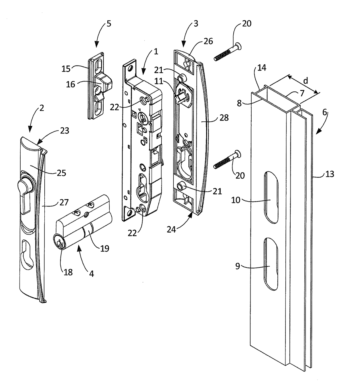
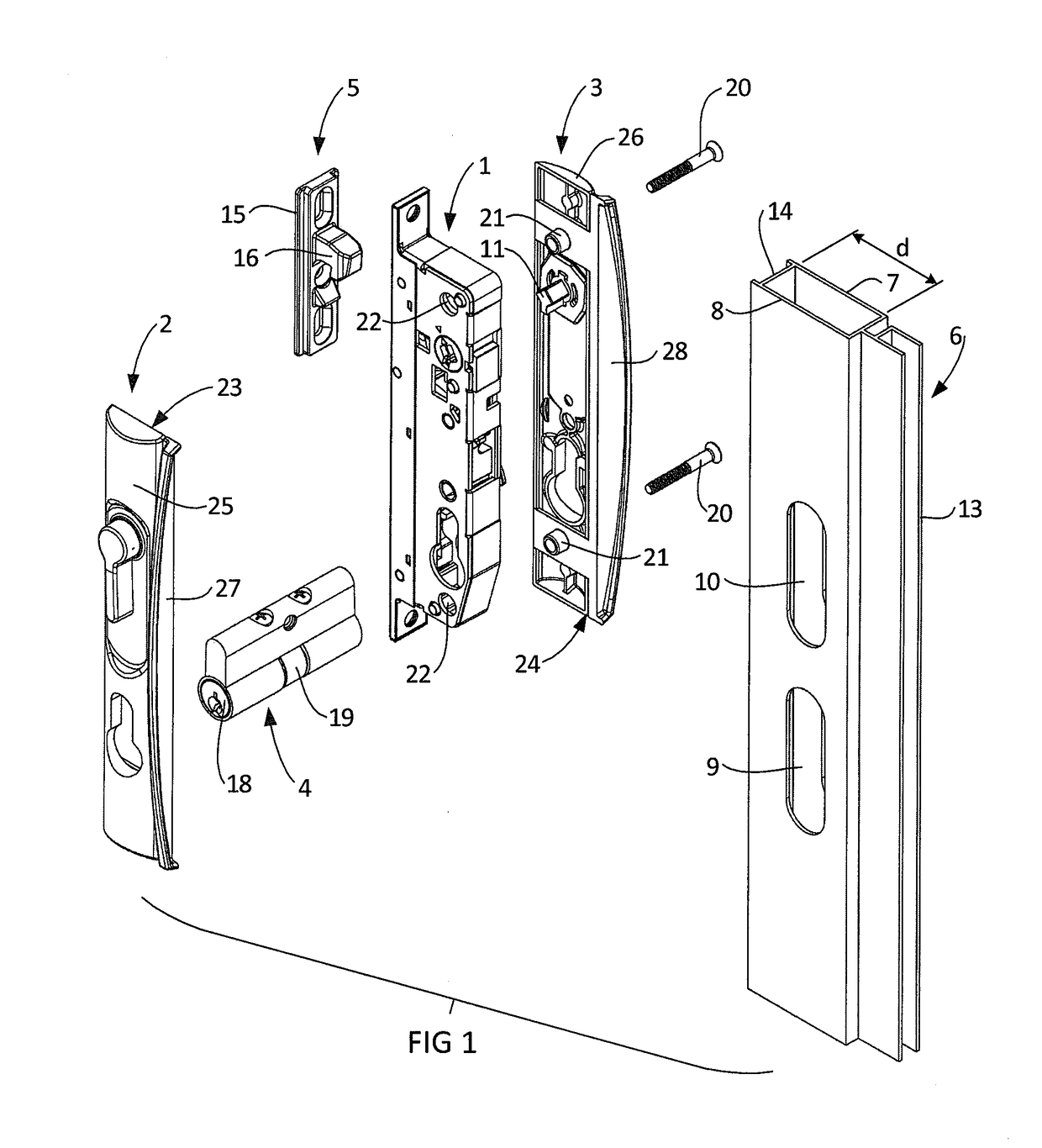
[0028]Referring firstly to FIG. 1 which illustrates in summary a latch assembly 1, outer door furniture 2, inner door furniture 3, a cylinder lock 4, a strike 5, and a door frame 6. The preferred example of the door frame illustrated is in the form of an extruded metal frame of a type often used for a security door. The invention may be suitable for other forms of door frame, however the latch assembly and latchset described is particularly suited to this form of door frame 6. This type of door frame 6 has a relatively small cavity depth d to accommodate the latch assembly. Also the opposed inner wall 7 and outer wall 8 of the door frame 6 have limited space to accommodate the inner door furniture 3 and outer door furniture 2.

[0029]The door frame 6 illustrated in FIG. 1 includes a lower oblong aperture 9 formed through the outer wall 8 to accommodate the cylinder lock 4. The door frame 6 illustrated also includes an upper oblong aperture 10 formed through the outer wall 8 thereof t...


PUM


Abstract

This invention relates to a latch assembly 1, and a latch set 1, 2, 3, 4 for use with a sliding door frame 6. The latch assembly 1 includes a housing 48, 49, and a bolt 17 pivotable relative to the housing 48, 49 on rotation of either one of a pair of actuator hubs 51, 52. The latch assembly 1 also includes a pair of locking hubs, 55, 54 which are also rotatable to adjust the lock mechanism between an active condition and an inactive condition.

Description

BACKGROUND OF THE INVENTION1. Field of the Invention[0001]This invention relates to a latch assembly and to a latchset for use with a sliding door. The invention has been developed for a particular application installed in a security sliding door with a frame of limited space, and it will be convenient to hereinafter describe the invention with reference to this particular application. It is to be appreciated however that the invention may have other applications.2. Description of Related Art[0002]A latch assembly for a security sliding door will generally include a housing and a bolt that is movable relative to the housing between a latch position and a release position. The bolt may be biased towards adopting the latch position under the influence of a spring. The latchset may include door furniture such as a hand operated snib lever, to move the bolt to a retracted position. A snib lock mechanism may also be included that is operable from an inner side of the door to hinder retra...

Claims


Application Information

Patent Timeline
Patent Type & Authority Applications(United States)
IPC IPC(8): E05B65/08E05B15/02E05B41/00E05B63/04E05C3/30E05B63/20
CPCE05B65/0811E05C3/30E05B63/20E05B41/00E05B63/04E05B15/02
Inventor LIN, MATTHEW
Owner ASSA ABLOY AUSTRALIA PTY LTD
Why Eureka
Try Eureka