
Multi-function person handling equipment

a multi-functional, person-handling technology, applied in medical science, ambulance service, nursing beds, etc., can solve the problems of time it takes to lift someone, possible injury, etc., to reduce the stress and strain on ems personnel, and reduce the time it takes

Active Publication Date: 2018-02-01
STRYKER CORP
View PDF0 Cites 13 Cited by
  • Summary
  • Abstract
  • Description
  • Claims
  • Application Information

AI Technical Summary

Benefits of technology

The patent text describes a device that allows for easy movement of a platform deck without interfering with the floor surface. The device has two legs that can be moved from a first position to a second position. The length of the legs is designed to match the length of the deck, so when the legs are moved, the deck can be raised to a vertical position without touching the floor. This feature makes it easy to move and use the platform deck in different situations.

Problems solved by technology

A common challenge in the emergency medical service (EMS) industry is to reduce the stress and strain on EMS personnel when handling people who need assistance.
For example, a common situation that can subject EMS personnel to undue stress, and possible injury, is when moving a person from one person handling apparatus, such as an emergency cot, to another person handling apparatus, such as a chair.
Further, when dealing with injured people, the time it takes to lift someone, for example, onto a backboard, and then transfer them onto a cot to get them into appropriate transport vehicle may be critical.

Method used


Image

  • Multi-function person handling equipment
  • Multi-function person handling equipment
  • Multi-function person handling equipment

Examples


second embodiment

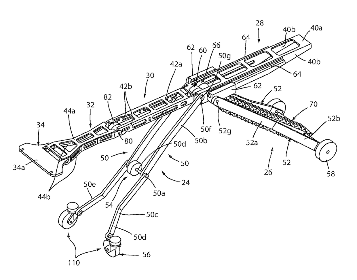
[0128]Referring to FIGS. 18 and 19, the numeral 256 generally designates a suitable caster assembly that may be mounted to legs 50 and used in lieu of the caster wheel assemblies described above in reference to person handling apparatus 20. As will be more fully explained below, each caster assembly 256 comprises a self-positioning caster assembly that will keep its swivel axis of rotation generally the same (e.g. vertical or nearly vertical) regardless of the position of the leg or the surface on which person handling apparatus 20 is transported or supported.

[0129]As best seen in FIG. 18, each caster wheel assembly 256 includes first and second caster wheels 256a and 256b. Each caster wheel 256a and 256b is rotatably mounted to a respective yoke 212a, 212b about an axis of rotation 256c, 256d, respectively, which axes are generally horizontal and form the rolling axes of the caster assembly 256. Yokes 212a, 212b in turn are commonly rotationally mounted to a bracket 260 by shafts o...

third embodiment

[0136]In a caster synchronizing assembly 464 (FIG. 21A), first and second force transmitting couplers 466, 468 may comprise pulleys (mounted about pins 212c, 212d), and a third force transmitting coupler 470 may comprise a belt that extends around and transmits the forces between first and second force transmitting couplers 466, 468 to thereby synchronize the swivel movement of the caster wheels.

[0137]In the second and third embodiment, the third force transmitting coupler is supported by the first and second force transmitting couplers and need not be mounted to the bracket of the respectively caster wheel assemblies.

[0138]Optionally, any of caster assemblies described above may incorporate a default position mechanism. For example, a suitable default position mechanism may include a magnet (or magnets) that is located such that when the caster assemblies are lifted from the supporting surface (e.g. such as a floor), the magnets will pull on the caster wheels so they are returned t...


PUM


Abstract

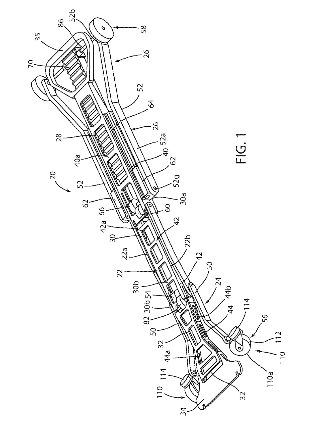
A person handling apparatus includes a deck with a seat section, a leg section, and a back section. The back section is pivotally mounted to the seat section. The leg section has a proximal end pivotally mounted to the seat section and a cantilevered end spaced a first distance from its proximal end. The seat section, the leg section, and the back section are arranged to lie in a common plane when the deck is in a supine configuration to support a person in a supine position. First and second leg assemblies are pivotally mounted to the deck to move between (1) first deployed positions wherein the first and second leg assemblies are angled relative to the deck when the deck is in the supine configuration to support the deck in a raised composition and (2) second deployed positions when the deck is supported in the chair configuration.

Description

RELATED APPLICATIONS[0001]This application claims the benefit of U.S. Prov. Appl. Ser. No. 62 / 369,417, filed on Aug. 1, 2016, which is incorporated by reference herein in its entirety.TECHNICAL FIELD AND BACKGROUND[0002]The present disclosure relates to a person handling equipment for handling a person, for example, when they need to be moved from a supine position to a seated position.[0003]A common challenge in the emergency medical service (EMS) industry is to reduce the stress and strain on EMS personnel when handling people who need assistance. For example, a common situation that can subject EMS personnel to undue stress, and possible injury, is when moving a person from one person handling apparatus, such as an emergency cot, to another person handling apparatus, such as a chair. Further, when dealing with injured people, the time it takes to lift someone, for example, onto a backboard, and then transfer them onto a cot to get them into appropriate transport vehicle may be cr...

Claims


Application Information

Patent Timeline
Patent Type & Authority Applications(United States)
IPC IPC(8): A61G1/017A61G5/06A61G1/02A61G7/10A61G7/16A61G1/013
CPCA61G1/017A61G7/16A61G1/013A61G5/006A61G7/1013A61G7/1038A61G5/061A61G1/0237A61G1/0243A61G1/04A61G1/0562A61G5/066A61G7/10
Inventor STRYKER, MARTIN W.LUCAS, ROSS TIMOTHY
Owner STRYKER CORP
Learn More