
Scroll compressor

a compressor and scrolling technology, applied in the direction of liquid fuel engines, machines/engines, rotary piston liquid engines, etc., can solve the problems of reducing the reliability of the compressor operation, wasting power consumption, and the compressor to fail to work normally, so as to improve the adjustment range of the sealing member, optimize the axial force of the scroll set, and facilitate the design of the force applying area

Active Publication Date: 2018-01-25
EMERSON CLIMATE TECH (SUZHOU) CO LTD
View PDF5 Cites 20 Cited by
  • Summary
  • Abstract
  • Description
  • Claims
  • Application Information

AI Technical Summary

Benefits of technology

The patent text aims to improve the reliability of a scroll compressor.

Problems solved by technology

However, with this design, in unfavorable operating conditions such as liquid strike, there is a possibility that the back pressure is reduced such that the orbiting scroll member and the non-orbiting scroll member cannot be axially engaged, which causes the compressor to fail to work normally and reduces reliability of operation of the compressor, and further causes a waste of power consumption.

Method used


Image

  • Scroll compressor
  • Scroll compressor
  • Scroll compressor

Examples


Embodiment Construction

[0034]The following description of the preferred embodiments is merely exemplary and is by no means intended to limit the present application and its application or usage. The like reference numerals are used to designate like parts throughout the drawings, and the description of the construction of the like parts will not be repeated.

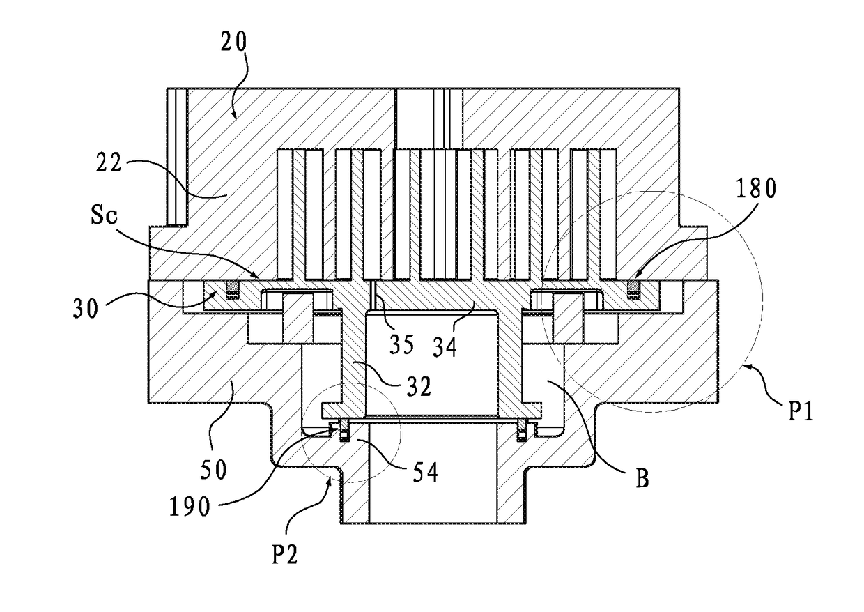
[0035]The basic construction and operation principle of the scroll compressor 1 to which the present application can be applied will be described below with reference to FIG. 1.

[0036]As shown in FIGS. 1 and 2, a scroll compressor (hereinafter also referred to as a compressor) 1 includes a substantially closed housing 10. The housing 10 defines an internal space of the compressor 1. In the example in the drawings, the housing 10 may consist of a generally cylindrical body portion 12, a top cover 14, and a bottom cover 16. These components of the housing 10 may, for example, be connected to each other by any suitable means such as welding, bolting, or th...


PUM


Abstract

A scroll compressor is provided, comprising: a compression mechanism comprising a non-orbiting scroll member and an orbiting scroll member, wherein the orbiting scroll member is axially displaceable between an engagement position and a disengagement position; a main bearing housing adapted to support the compression mechanism; a back pressure chamber formed between the orbiting scroll member and the main bearing housing, wherein the back pressure chamber is in communication with at least one of the compression chambers via a communication passage provided in the orbiting scroll member or the non-orbiting scroll member and is adapted to apply a back pressure to the orbiting scroll member to bias the orbiting scroll member toward the engagement position; and a first sealing means provided between the back pressure chamber and a suction zone of the compression mechanism and capable of maintaining sealing when the orbiting scroll member is axially displaced.

Description

[0001]This application claims the benefit of priorities to Chinese Patent Application No. 201510058036.X titled “SCROLL COMPRESSOR”, filed with the Chinese State Intellectual Property Office on Feb. 4, 2015, and Chinese Patent Application No. 201520079596.9 titled “SCROLL COMPRESSOR”, filed with the Chinese State Intellectual Property Office on Feb. 4, 2015, the entire disclosures of which are incorporated herein by reference.FIELD OF THE INVENTION[0002]The present application relates to a scroll compressor.BACKGROUND OF THE INVENTION[0003]The contents of this section only provide background information related to this disclosure, which may not constitute the prior art.[0004]It is known that in a scroll compressor having an axial flexibility, a back pressure chamber is provided on an orbiting scroll member side so as to provide the orbiting scroll member with a back pressure which enables the orbiting scroll member to be axially engaged with a non-orbiting scroll member. However, wi...

Claims


Application Information

Patent Timeline
Patent Type & Authority Applications(United States)
IPC IPC(8): F04C27/00F01C17/06F04C18/02
CPCF04C27/003F04C18/0215F01C17/066F04C18/0269F04C2240/50F01C19/005F04C27/005F04C18/0253F04C28/22
Inventor HUANG, YOULINGYANG, CHUNZENG, DANG
Owner EMERSON CLIMATE TECH (SUZHOU) CO LTD
Learn More