
Credit Loop Deadlock Detection and Recovery in Arbitrary Topology Networks

Active Publication Date: 2018-01-18
MELLANOX TECHNOLOGIES LTD
View PDF42 Cites 7 Cited by
  • Summary
  • Abstract
  • Description
  • Claims
  • Application Information

AI Technical Summary

Benefits of technology

The invention provides algorithms to detect and correct impaired traffic through a data switching network, including recovery from credit loop deadlock for arbitrary network topologies and routing protocols. These algorithms can be implemented in commodity switch hardware and require negligible additional control bandwidth. They avoid packet loss after a deadlock occurs. The method also includes identifying flows that traverse certain ports and rerouting them via alternate paths to destinations with minimum cost metrics. Additionally, the method includes increasing an available buffer size in certain ports.

Problems solved by technology

Even with reliable transport protocols, such as TCP, dropping packets results in bandwidth decrease, significant completion time increase and statistical tail, especially with short-lived flows.
Although lossless networks can improve end-to-end network performance, without careful design and operation, they can suffer from in-network deadlocks, caused by cyclic buffer dependencies.
A credit loop deadlock occurs when all the switch buffers on the sequence become full and no traffic can be propagated.
Although existing credit loops rarely deadlock, when they do they can block large parts of the network.
Previous works have suggested credit loop avoidance by central routing algorithms, but these assume specific topologies and are slow to react to failures.
However, these methods are all based on a central controller to calculate the forwarding rules that avoid credit loops and thus are slow to respond to failures and work only in SDN-like environments.

Method used


Image

  • Credit Loop Deadlock Detection and Recovery in Arbitrary Topology Networks
  • Credit Loop Deadlock Detection and Recovery in Arbitrary Topology Networks
  • Credit Loop Deadlock Detection and Recovery in Arbitrary Topology Networks

Examples


example 1

ker Algorithm

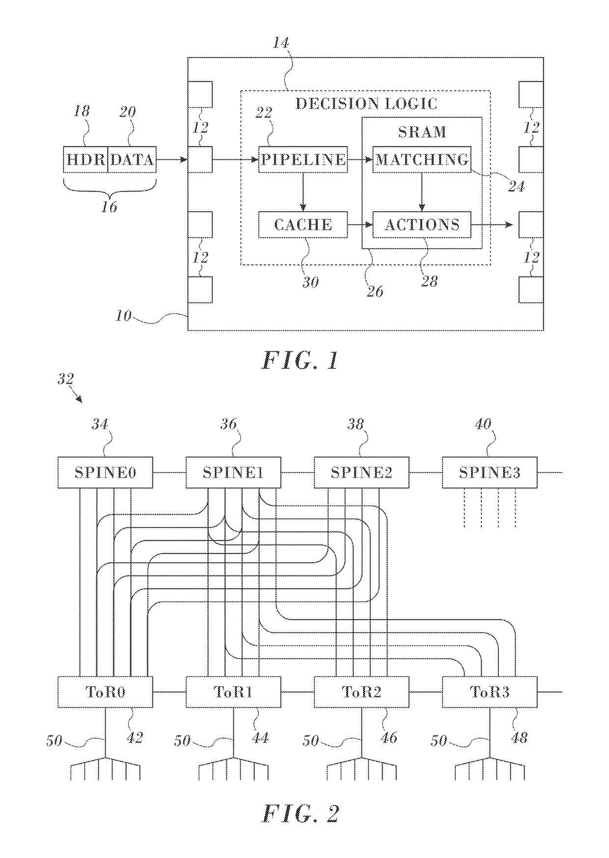
[0101]The Loop Breaker algorithm algorithms was implemented and evaluated using a Soft-ware Development Kit (SDK) of the Mellanox Spectrum™ Ethernet switch. The SDK allows access to egress queue length and the outgoing bandwidth samples. These values are monitored to determine if the egress port is suspected to be blocked.

[0102]In parallel, a flow monitoring process stores the ingress and egress ports for recent flows that are transmitted through the switch. Each flow is identified by a 5-tuple (source, destination IP addresses, source and destination layer ports and layer 4 protocol), which fields that are used by the ECMP hashing function. A preferable alternative implementation is to rely on an elephant flows detection mechanism if it is available in the switch hardware.

[0103]As described above, when a new deadlock-suspected port is detected, a new CLCM packet with a random SPUID is created and sent by the switch CPU. The switch is also configured to trap incoming CL...

example 2

Breaker

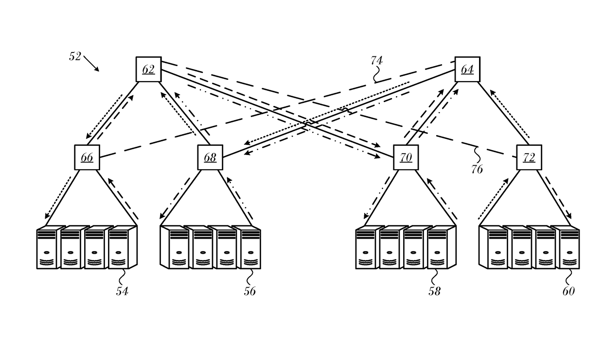
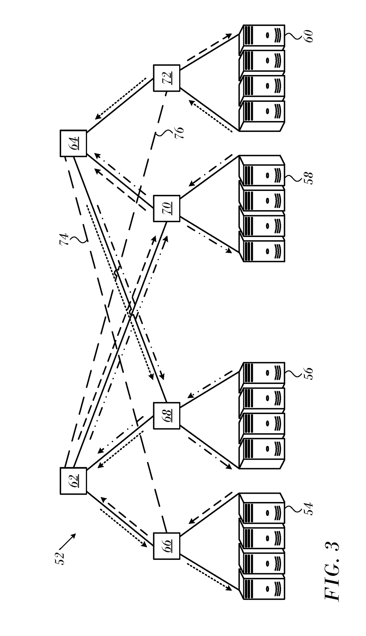
[0110]Reference is now made to FIG. 11, which is a diagram of a 3-level fat-tree 202 in which the Deadlock Breaker algorithm was simulated in accordance with an embodiment of the invention. In this Example, the Deadlock Breaker algorithm was implemented in a network simulator and tested on the network presented in FIG. 11. Wiring mistakes, indicated by dashed lines 204, makes this fat-tree prone to credit loops, even when routed with a minimal hop routing algorithm. To cause a deadlock we introduced nine flows: flows 9 ! 15; 13 ! 32; 30 ! 17 form the credit loop; and flows 14 ! 15; 16 ! 15; 18 ! 17; 20 ! 17; 29 ! 32; 31 ! 32 create the backpressure required to fill up the buffers of switches participating in the credit loop. We simulated the network with and without the Deadlock Breaker algorithm and measured the output bandwidth of the flows on the credit loop.

[0111]Reference is now made to FIG. 12, which is a set of graphical plots of a simulation of the scenario shown in F...


PUM


Abstract

A credit loop that produces a deadlock is identified in a network of switches that are interconnected for packet traffic flows therethrough. The identification is carried out by periodically transmitting respective credit loop control messages from the loop-participating switches via their deadlock-suspected egress ports to respective next-hop switches. The CLCMs has switch port-unique identifiers (SPUIDs). The loop is identified when in one of the next-hop switches the SPUID of a received CLCM is equal to the SPUID of a transmitted CLCM thereof. A master switch is selected for resolving the deadlock.

Description

CROSS-REFERENCE TO RELATED APPLICATIONS[0001]This application claims the benefit of U.S. Provisional Application No. 62 / 362,072, filed 14 Jul. 2016, which is herein incorporated by reference.COPYRIGHT NOTICE[0002]A portion of the disclosure of this patent document contains material that is subject to copyright protection. The copyright owner has no objection to the facsimile reproduction by anyone of the patent document or the patent disclosure, as it appears in the Patent and Trademark Office patent file or records, but otherwise reserves all copyright rights whatsoever.BACKGROUND OF THE INVENTION1. Field of the Invention[0003]This invention relates to data switching networks. More particularly, this invention relates to congestion avoidance and recovery in data switching networks.2. Description of the Related Art[0004]The meanings of certain acronyms and abbreviations used herein are given in Table 1.TABLE 1Acronyms and AbbreviationsCEEConverged Enhanced EthernetCLCMCredit Loop Co...

Claims


Application Information

Patent Timeline
IPC IPC(8): H04L12/801H04L12/707H04L12/863H04L45/24H04L47/52
CPCH04L47/10H04L47/627H04L47/524H04L47/39H04L45/22H04L45/18H04L45/28H04L45/243
Inventor SHPINER, ALEXANDERZAHAVI, EITANZDORNOV, VLADIMIRANKER, TALKADOSH, MATTY
Owner MELLANOX TECHNOLOGIES LTD
Learn More