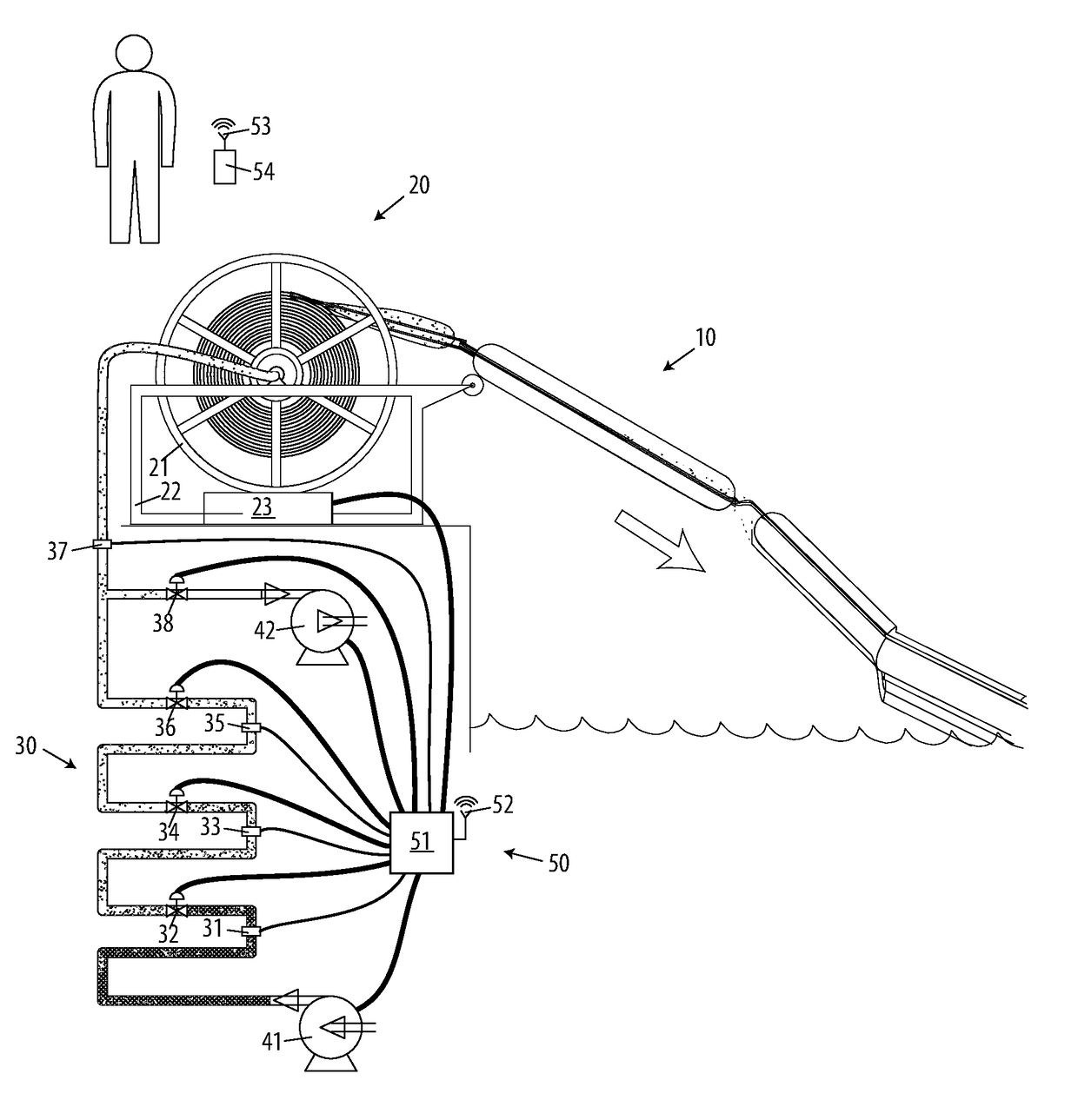

On-board spool-able re-useable containment boom and control system

Inactive Publication Date: 2018-01-18
MILLER MICHAEL T +1
View PDF7 Cites 5 Cited by
  • Summary
  • Abstract
  • Description
  • Claims
  • Application Information

AI Technical Summary

Benefits of technology

The invention provides an on-board spool-able re-useable containment boom for a waterborne vessel that can be easily deployed and recovered for training and testing purposes. The boom can be quickly inflated or deflated and is adaptable to changing circumstances and provides an effective response to oil spills or other contaminate spills. The control system ensures proper inflation and deflation during deployment and recovery. The invention allows for quick training and testing of personnel and equipment and provides more effective responses to actual oil spills.

Problems solved by technology

The patents cited above each contemplate inflation from the leading edge of the boom one section at a time, and do not disclose any method of the continuous inflation of the boom from a single inflatable gas source originating at the lagging last-off section of boom that runs concurrently with the boom.
Nor do these patents disclose inflation from an inflatable gas source already connected to the boom prior to deployment.
This greatly increases the time and complexity of inflation and deployment.
The above patents and current practices are employed to respond to discharges of floatable material on water surfaces, such as hydrocarbons, but thus fail to disclose a rapidly deployable system with a retaining boom that can be deployed from a single point, without need for multiple power sources, and which can withstand ruptures and leaks.
The patents recited above also are restricted in the functional length of a single floating barrier, or boom, because they lack an inflatable gas delivery line that runs concurrently with the entire length of boom.
This delay results in increased, un-contained discharges of toxins onto the water.

Method used


Image

  • On-board spool-able re-useable containment boom and control system
  • On-board spool-able re-useable containment boom and control system
  • On-board spool-able re-useable containment boom and control system

Examples


Embodiment Construction

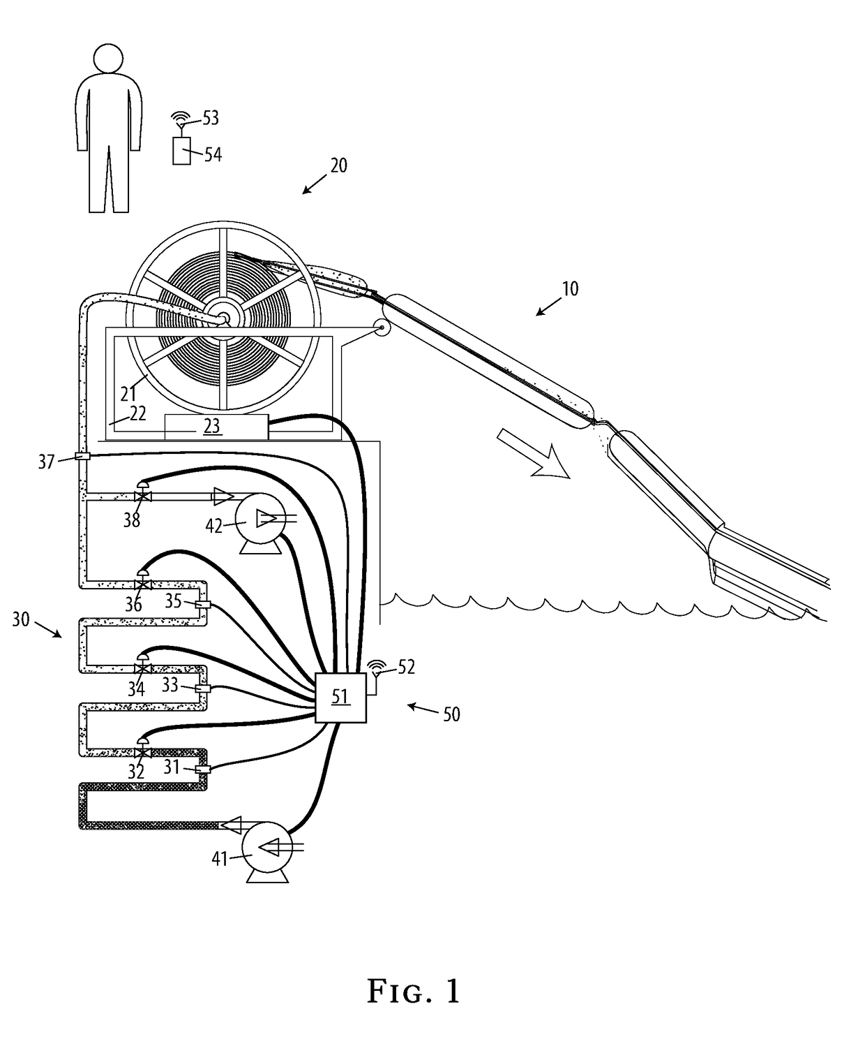
[0043]Referring to FIG. 1, our invention provides an on-board spool-able re-useable containment boom 10 capable of being deployed and recovered for training and testing purposes, and of being deployed in the event of an oil spill or similar floating contamination of water, under the control of a pneumatic control system 50 monitored and controlled by an operator through a control display 54.

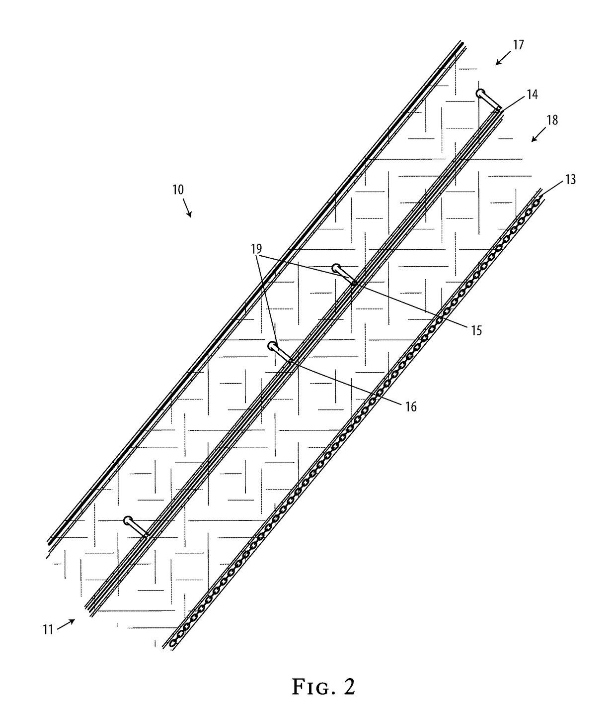
[0044]Referring to FIG. 3 and FIG. 4, the on-board spool-able re-useable containment boom 10 has spool-able re-inflatable float sections 17 which are sequentially inflated during deployment and sequentially deflated during recovery, causing the containment boom to float in the proper orientation when inflated, with the spool-able containment skirt 18 suspended below the surface of the water, and causing the containment boom to lie substantially flat and capable of being spooled and stored when deflated. When deployed, the containment boom sits in a substantially vertical orientation with an upper...


PUM


Abstract

An on-board spool-able re-useable containment boom for a waterborne vessel that lies substantially flat and capable of being spooled when deflated and floats in the proper orientation when inflated, that has spool-able re-inflatable float sections which are sequentially inflated during deployment and sequentially deflated during recovery, that can be repeatedly deployed and recovered for the purposes of training and testing, and that can be deployed immediately upon occurrence of an oil spill from a waterborne vessel because of its on-board location and its rapid deployment, and a control system for proper inflation and deflation of spool-able re-useable containment boom during deployment and recovery.

Description

CROSS-REFERENCE TO RELATED APPLICATIONS[0001]This application is a continuation-in-part of my co-pending application Ser. No. 15 / 235,306, filed Aug. 12, 2016 for an “On-Board Re-Inflatable Containment Boom and Control System,” which is a continuation of my application Ser. No. 14 / 730,778, filed on Jun. 4, 2015 for an “On-Board Re-Inflatable Containment Boom and Control System,” issued on Nov. 8, 2016 as U.S. Pat. No. 9,487,926, which was a continuation-in-part of my application Ser. No. 12 / 902,282, filed on Oct. 12, 2010 for an “Onboard Oil Containment System, issued on Dec. 8, 2015 as U.S. Pat. No. 9,206,575, the full disclosures of which are incorporated by reference herein and priority of which is hereby claimed.BACKGROUND[0002]This invention provides an on-board spool-able re-useable containment boom for a waterborne vessel that can be repeatedly deployed and recovered for the purposes of training and testing, and that can be deployed immediately upon occurrence of an oil spill ...

Claims


Application Information

Patent Timeline
IPC IPC(8): E02B15/08E02B15/04E02B15/06G05D16/20
CPCE02B15/0807E02B15/0864E02B15/0842E02B15/0828E02B15/047E02B15/0871E02B15/06G05D16/2026E02B15/0814E02B15/0835Y02A20/204
Inventor MILLER, MICHAEL T.HALL, TERRY
Owner MILLER MICHAEL T
Learn More