Distortion rectification method and terminal
a technology of distortion correction and terminal, applied in the field of distortion correction methods and terminals, can solve the problems of distortion generation, shooting range subject to a certain limitation, etc., and achieve the effect of reducing the degree of distortion in the region
- Summary
- Abstract
- Description
- Claims
- Application Information
AI Technical Summary
Benefits of technology
Problems solved by technology
Method used
Image

Examples
first embodiment
[0078]Referring to FIGS. 1 to 5, a distortion rectification method and a terminal in accordance with the present disclosure are disclosed.
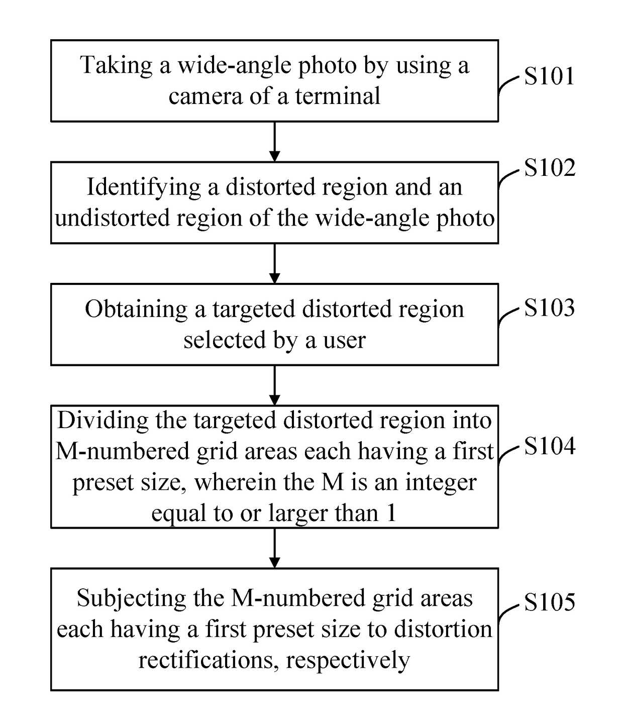
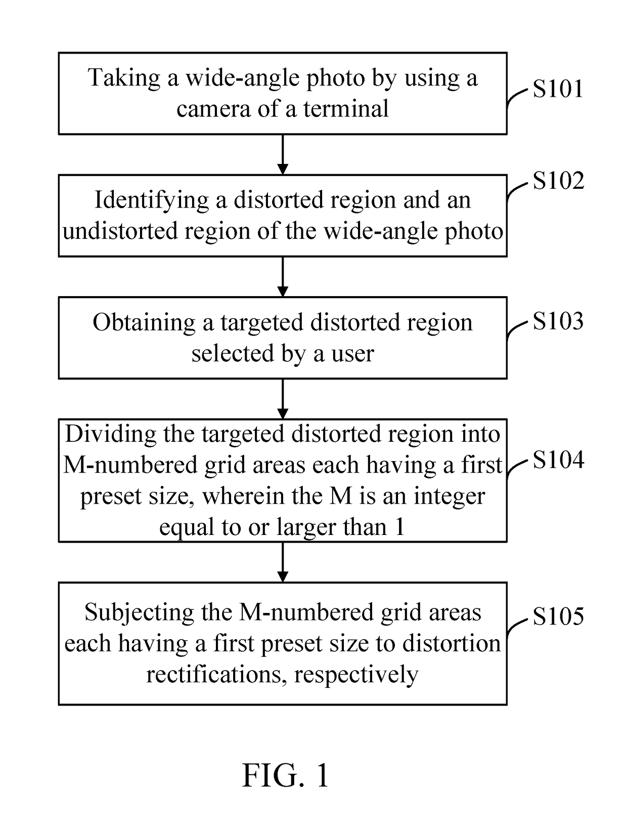
[0079]Please refer to FIG. 1. FIG. 1 shows a flow chart of a distortion rectification method provided by a first embodiment of the present disclosure, which includes the following blocks.
[0080]In block S101, a wide-angle photo is taken by using a camera lens of a terminal.
[0081]The terminal can use the camera lens of the terminal to shoot a wide-angle picture.
[0082]As a possible embodiment, the terminal can determine an angular range to be shot before the terminal uses the camera lens thereof to take a wide-angle photo. When the user activates the camera lens of the terminal, the user can adjust the angular range of shooting according the scene / object that the user wants to take in the photo. The angular range to be shot is ascertained by the user according to the size of the region that the scene / object occupies. The terminal can first obtain the...
second embodiment
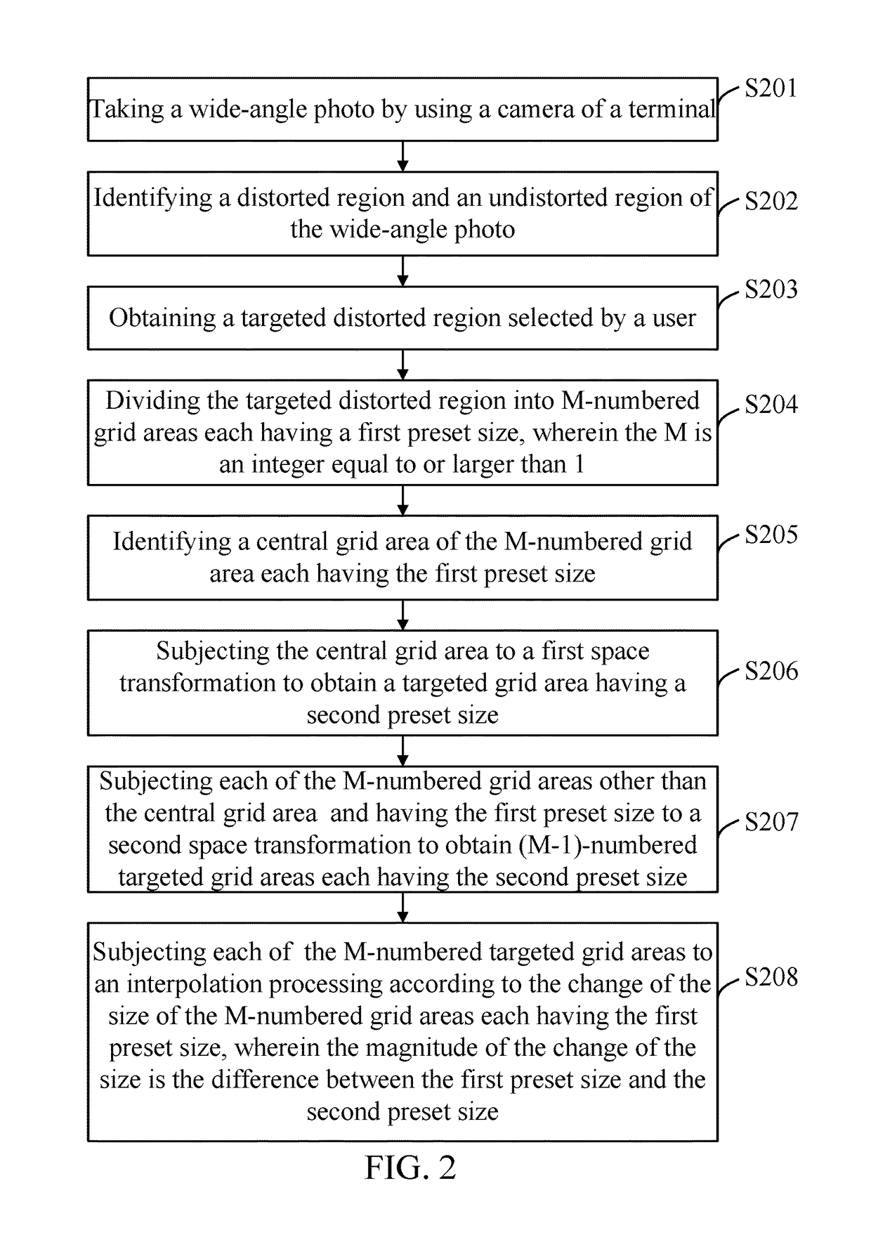
[0093]Referring to FIG. 2, FIG. 2 is a flow chart of a method for distortion rectification according to the present disclosure. The distortion correction method disclosed by this embodiment includes the following blocks.
[0094]In block S201, a camera lens of a terminal is used to take a wide-angle photo.
[0095]The terminal can use a camera lens thereof to take the wide-angle photo.
[0096]As a possible embodiment, the terminal can make sure the angular range that the camera lens of the terminal is intended to shoot, before the camera lens of the terminal is used to take the photo. When the user activates the camera lens of the terminal, the user can decide the scene / object to be shot to adjust the angular range of the shooting. A predetermined angular range of shooting is ascertained by the user according to the size of the scene / object in the background. The terminal can obtain the touch instruction related to the angular range of shooting decided by the user and ascertain the predeter...
third embodiment
[0115]Referring to FIG. 3, FIG. 3 is a flow chart of a method for distortion rectification according to the present disclosure. The distortion correction method disclosed by this embodiment includes the following blocks.
[0116]In block S301, a camera lens of a terminal is used to take a wide-angle photo.
[0117]The terminal can use a camera lens thereof to take the wide-angle photo.
[0118]As a possible embodiment, the terminal can make sure the angular range that the camera lens of the terminal is intended to shoot, before the camera lens of the terminal is used to take the photo. When the user activates the camera lens of the terminal, the user can decide the scene / object to be shot to adjust the angular range of the shooting. A predetermined angular range of shooting is ascertained by the user according to the size of the scene / object in the background. The terminal can obtain the touch instruction related to the angular range of shooting decided by the user and ascertain the predeter...
PUM
 Abstract
Description
Claims
Application Information
 - R&D
- Intellectual Property
- Life Sciences
- Materials
- Tech Scout
- Unparalleled Data Quality
- Higher Quality Content
- 60% Fewer Hallucinations
Browse by: Latest US Patents, China's latest patents, Technical Efficacy Thesaurus, Application Domain, Technology Topic, Popular Technical Reports.
© 2025 PatSnap. All rights reserved.Legal|Privacy policy|Modern Slavery Act Transparency Statement|Sitemap|About US| Contact US: help@patsnap.com