Vis-nir equipped soil penetrometer

a soil penetrometer and vis-nir technology, applied in the field of soil penetrometers, can solve the problems of many limitations and challenges of the vis-nir-based instruments for in situ soil characterization, and achieve the effect of improving the ability

Active Publication Date: 2017-12-28
TEXAS A&M UNIVERSITY +1
View PDF2 Cites 16 Cited by
  • Summary
  • Abstract
  • Description
  • Claims
  • Application Information

AI Technical Summary

Benefits of technology

[0009]Advantageously, the subject invention enhances the ability to collect in situ high resolution reflectance data for soil constituent interpretation and quantification and can be widely used by researchers in fields such as natural resource management, hydrologic modeling, soil mapping, and precision agriculture.

Problems solved by technology

However, existing Vis-NIR-based instruments for in situ characterization of soil have many limitations and face challenges when attempting to obtain high resolution spatial and temporal soil data intended for precision agriculture, soil survey and mapping, land resource management, and soil modeling.

Method used


Image

  • Vis-nir equipped soil penetrometer
  • Vis-nir equipped soil penetrometer
  • Vis-nir equipped soil penetrometer

Examples


embodiment 1

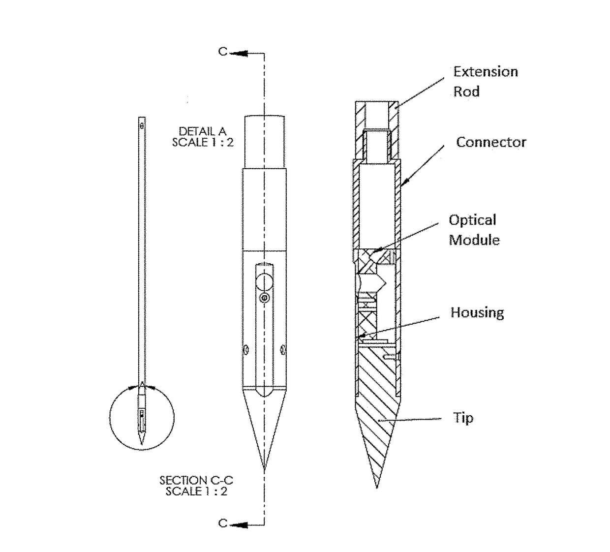
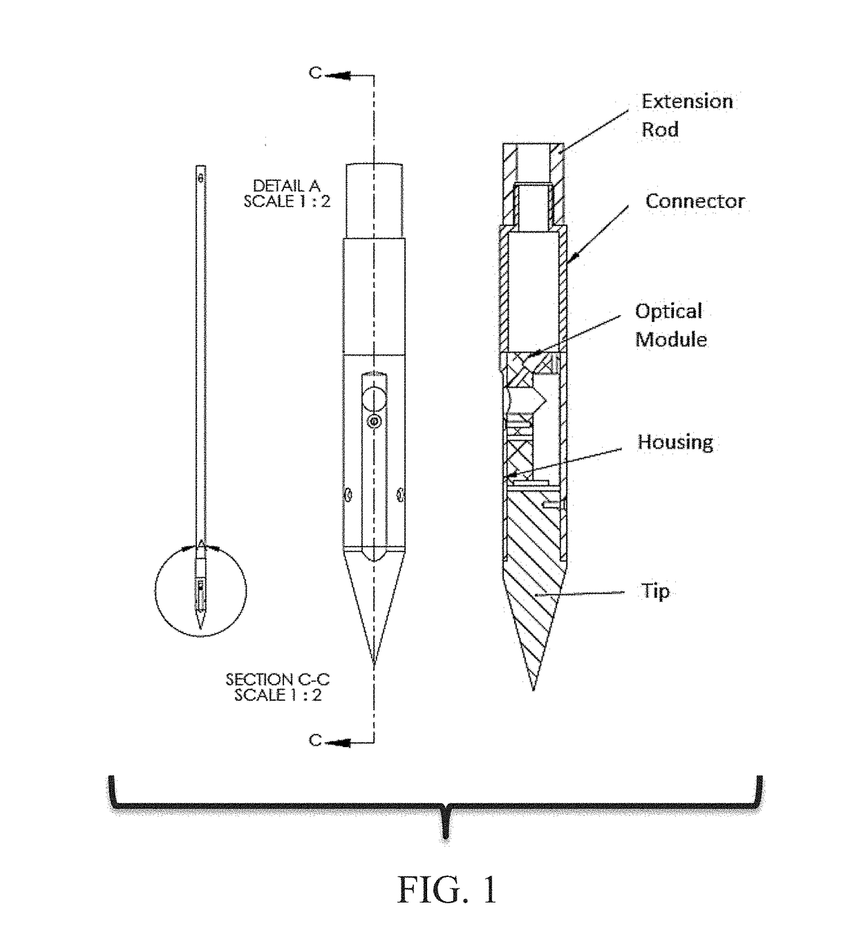
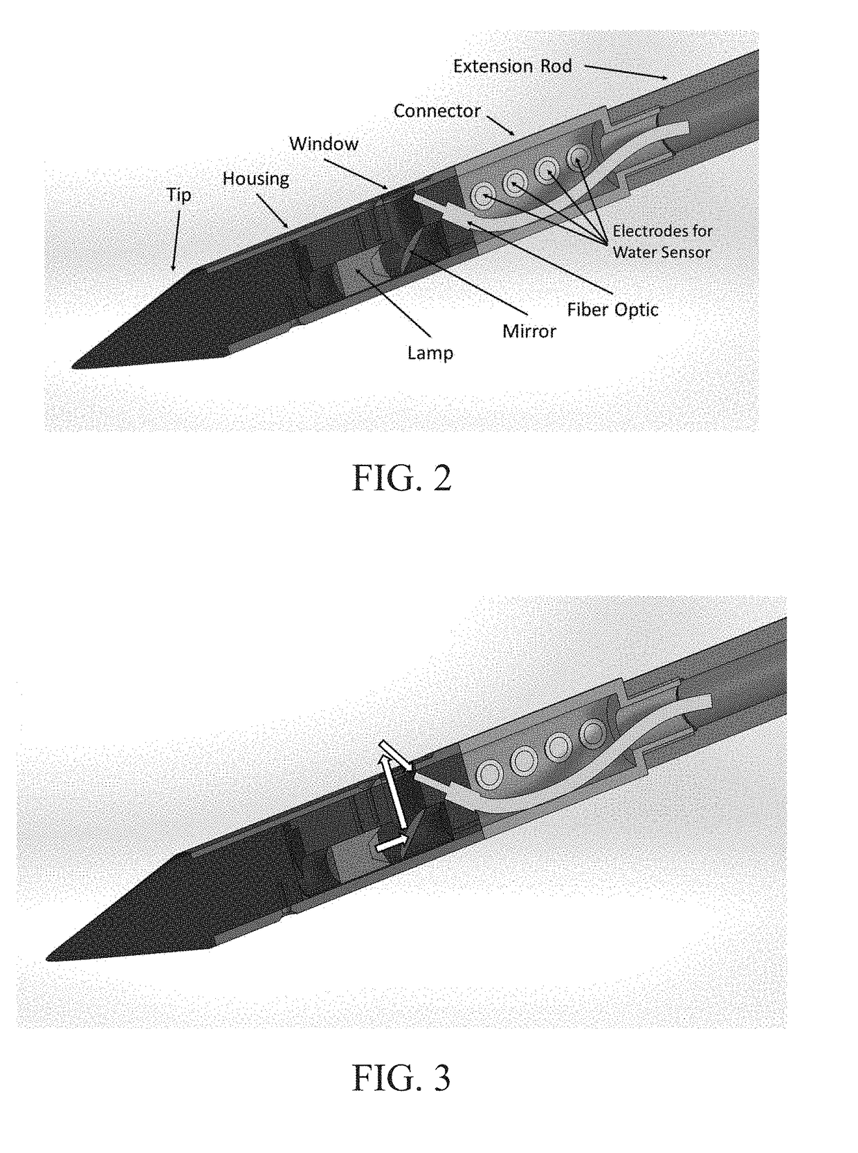
[0050]A soil penetrometer, comprising:[0051]a conical tip capable of penetrating into a soil sample;[0052]a tubular housing connected to the conical tip at one end;[0053]a tubular connector attached to the tubular housing at one end; and[0054]a tubular extension rod capable of being detachably connected to the connector at the end opposite to the tubular housing and detachably connected to another device or a combination of devices at the end opposite to the connector,[0055]wherein the tubular housing comprises:[0056]a transparent window built into the wall thereof, and[0057]an optical module comprising a light-emitting device, a mirror capable of reflecting light (and / or configured to reflect light) generated by the light-emitting device, and a fiber optic sensor, wherein the sensor is positioned in the vicinity of the transparent window to receive signals reflected by the soil sample and transmit the signals to a spectrometer.

embodiment 2

[0058]The penetrometer according to embodiment 1, wherein the connector encloses one or more sensing devices.

embodiment 3

[0059]The penetrometer according to any of embodiments 1-2, comprising a moisture sensor enclosed in the connector.


PUM

PropertyMeasurementUnit
diameteraaaaaaaaaa
inner diameteraaaaaaaaaa

Abstract

Soil penetrometers capable of measuring soil reflectance along the direction of insertion of the penetrometer are provided. The penetrometer can house an array of sensors, such as, for example, a Vis-NIR reflectance sensor, a load cell, a displacement sensor, and a moisture sensor. The reflectance data collected using the penetrometer can allow the interpretation and quantification of soil constituents and contaminants at high vertical resolution, such as 3 cm or more.

Description

CROSS-REFERENCE TO RELATED APPLICATION[0001]The present application claims the benefit of U.S. Provisional Application Ser. No. 62 / 353,716, filed Jun. 23, 2016, which is incorporated herein by reference in its entirety, including any figures, tables, and drawings.GOVERNMENT SUPPORT[0002]The subject invention was made with government support under 68-7482-2-39 awarded by USDA Natural Resources Conservation Services (NRCS), USDA-NIFA Award No. 2011-67003-30341, and under DE-FC26-05NT42587 awarded by U.S. Department of Energy National Energy Technology Laboratory to Dr. David Joseph Brown et al. The government has certain rights in the invention.BACKGROUND OF INVENTION[0003]Visible and near infrared reflectance spectroscopy (Vis-NIR) is widely used as a rapid and cost-effective technique for quantitative analysis of many soil properties. However, existing Vis-NIR-based instruments for in situ characterization of soil have many limitations and face challenges when attempting to obtain h...

Claims


Application Information

Patent Timeline
Patent Type & Authority Applications(United States)
IPC IPC(8): E02D1/02G01J3/10G01J3/02G01N33/24G01N21/01
CPCE02D1/027G01N33/246G01J3/0291G01N21/01G01J3/0208G01J3/0272G01J3/108G01N21/8507G01N33/24
Inventor MORGAN, CRISTINEGE, YUFENGBROWN, DAVIDBRICKLEMYER, ROSS
Owner TEXAS A&M UNIVERSITY
Why Eureka
Try Eureka