
Walk power mower having forward and reverse traction drive

Active Publication Date: 2017-12-28
TORO CO THE
View PDF3 Cites 5 Cited by
  • Summary
  • Abstract
  • Description
  • Claims
  • Application Information

AI Technical Summary

Benefits of technology

The invention relates to a walk power mower which has a deck with a cutting blade and a handle for the user to guide and manipulate the deck while it moves over the ground. The mower has a traction drive system with two transmissions that power the wheels on the deck. The user can activate the first transmission to move the mower forward or the second transmission to move it rearward by sliding the handle grip. The technical effect is a more intuitive and efficient way for the user to control the mower's motion.

Problems solved by technology

It can be difficult or is undesirable for some users to manually push a walk power mower over the ground in order to cut one's lawn.
It is tiring to do so, particularly when the area being mowed is either large, hilly, or both.
However, once this patch of grass is cut, the user must pull back on the handle to pull the mower out from under the branches of the bush.
While the traction drive system is designed with a one way clutch to allow the drive wheels to free-wheel during reverse motion so that the user is not pulling back against the resistance provided by the gearing in the traction drive system, the drive wheels of the mower are typically unpowered during this reverse motion.
As a result, many users end up having to manhandle or wrestle the mower back in this reverse motion scenario.
This requires the user to expend physical energy and for some users accomplishing manual reverse motion of the mower may be difficult or impossible in some situations.
This difficulty is exacerbated for those users in which trimming operations requiring reverse motions of the mower are numerous or are required on difficult terrain.
For example, in trimming beneath a bush, pulling back on the mower is even more difficult if the user has to pull the mower back up a slope to get it out from under the branches of the bush.

Method used


Image

  • Walk power mower having forward and reverse traction drive
  • Walk power mower having forward and reverse traction drive
  • Walk power mower having forward and reverse traction drive

Examples


Embodiment Construction

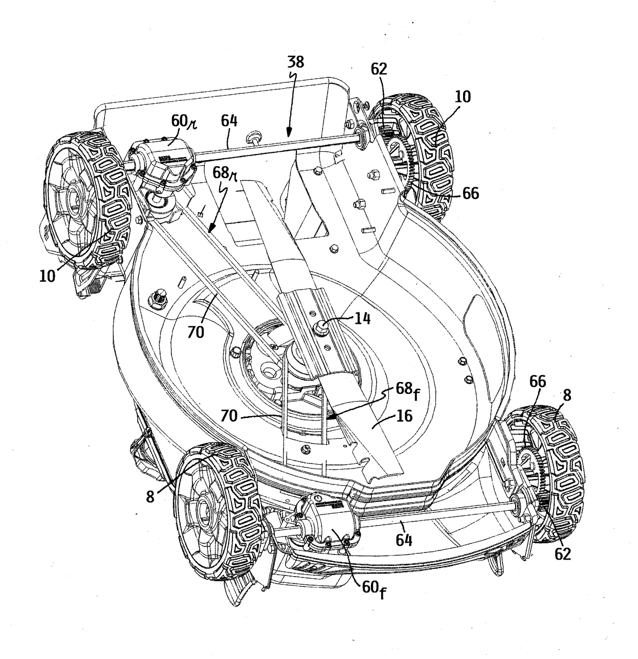
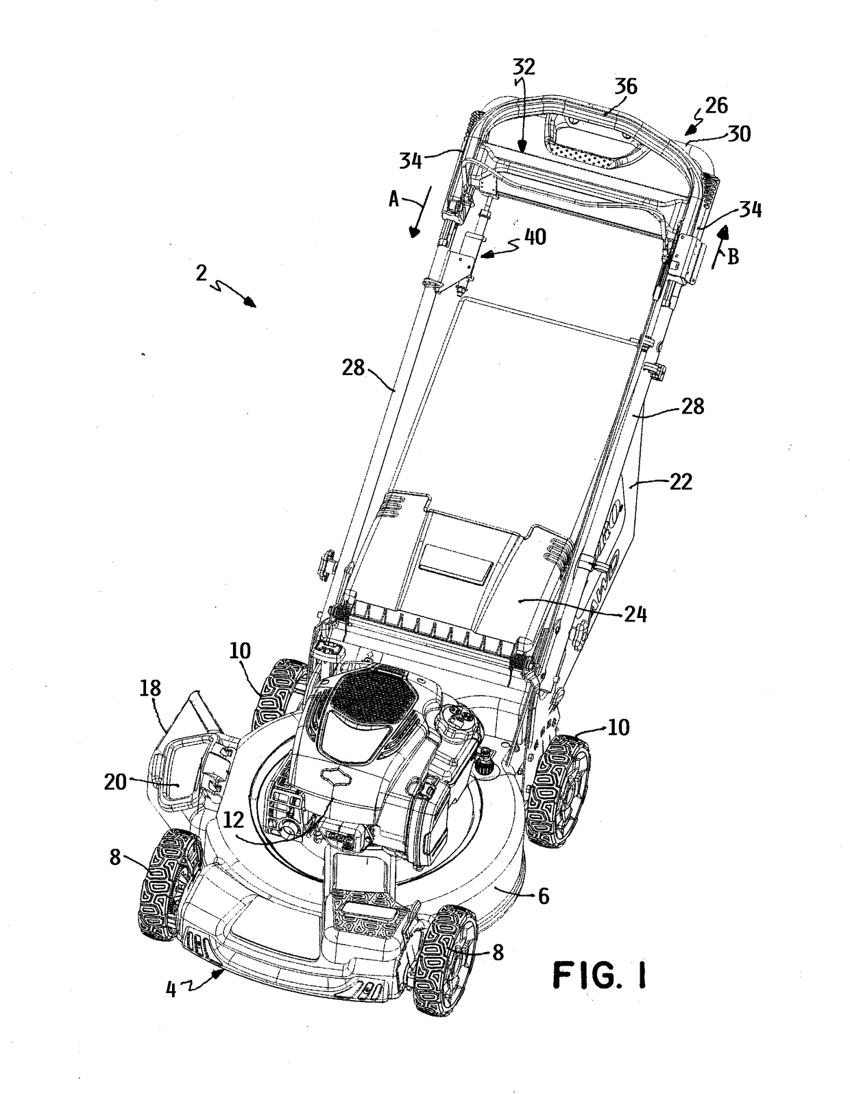
[0014]One embodiment of a walk power mower 2 according to this invention is illustrated in FIG. 1. Mower 2 comprises a cutting deck 4 that is formed with a generally toroidal cutting chamber 6 that faces downwardly and is open at its bottom. Deck 4 is supported for rolling over the ground by a pair of front wheels 8 and a pair of rear wheels 10. A prime mover 12, such as an internal combustion engine, is carried on top of deck 4. Referring now to FIG. 3, the drive shaft 14 of the prime mover extends vertically downwardly with its lower end extending into cutting chamber 6. A horizontal cutting blade 16 is positioned within cutting chamber 6 and is removably secured to the lower end of drive shaft 14 to rotate in a generally horizontal cutting plane to cut grass.

[0015]Referring again to FIG. 1, mower 2 is a three-in-one mower having side discharge, rear bagging and mulching modes of operation. In the side discharge mode, a side discharge chute 18 can be mated with a side discharge op...


PUM


Abstract

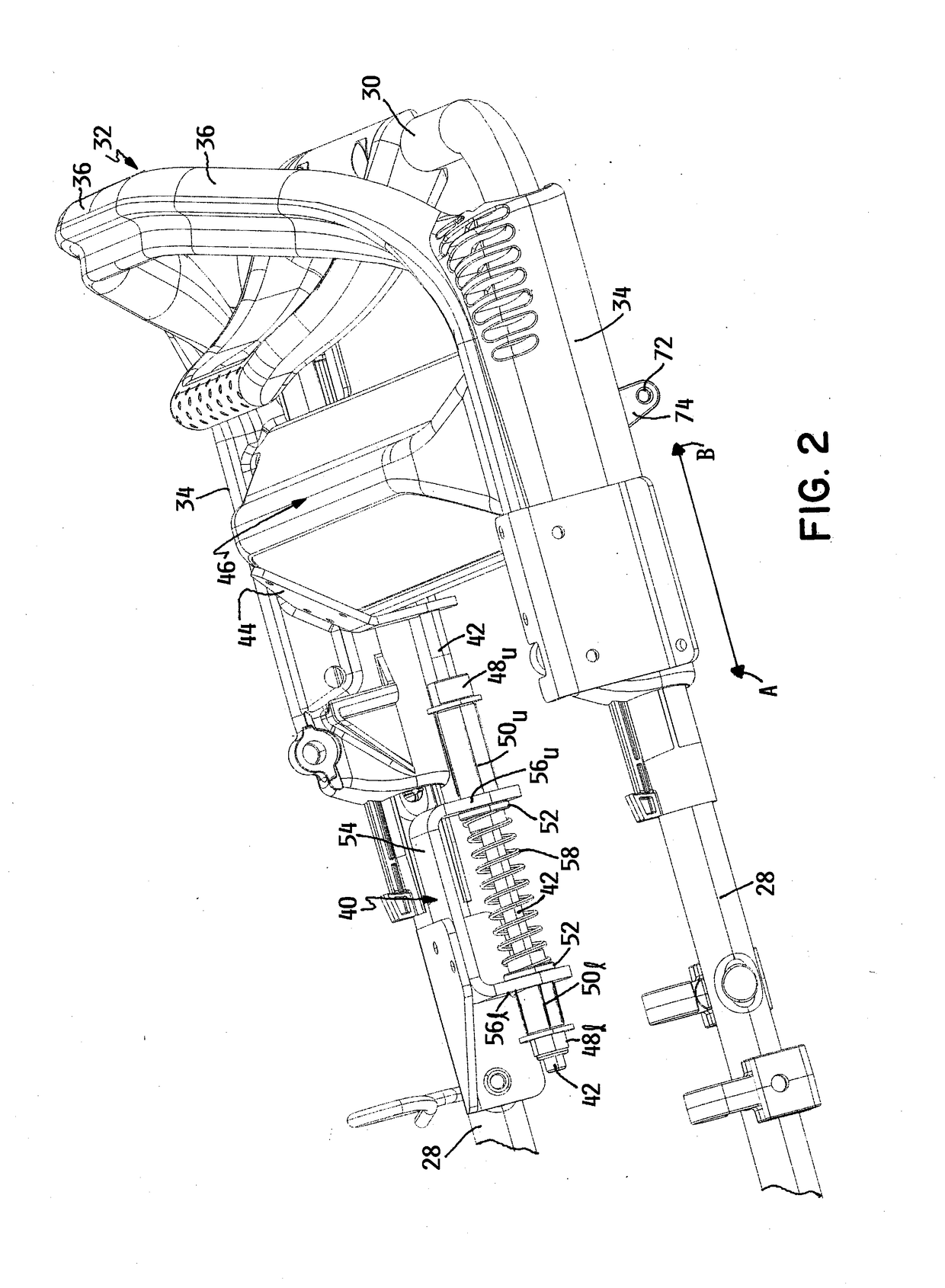
A walk power mower has a traction drive system that includes a front transmission powering a pair of front wheels and a rear transmission powering a pair of rear wheels. A first one of the transmissions provides forward motion of the mower when it is active and a second one of the transmissions provides rearward motion of the mower when it is active. A slidable handle grip on the handle having a cross bar long enough to be gripped by both hands of the user activates the first one of the transmission when it is slid downwardly on a handle out of a neutral position thereof. The slidable handle grip activates the second one of the transmissions when it is slid upwardly on the handle out of the neutral position.

Description

TECHNICAL FIELD[0001]This invention relates to a walk power mower for cutting grass and, more particularly, to a traction drive system for self-propelling the mower.BACKGROUND OF THE INVENTION[0002]Self-propelled walk power mowers are well known for cutting grass. For example, such mowers are commonly used by property owners, such as homeowners, to cut their lawns. Such mowers have a cutting deck that houses a rotary grass cutting blade. The deck is supported by a plurality of wheels for rolling over the ground. A handle extends upwardly and rearwardly from the deck. A user who walks on the ground behind the deck grips a handle grip of the handle to manipulate and guide the mower during a grass mowing operation.[0003]It can be difficult or is undesirable for some users to manually push a walk power mower over the ground in order to cut one's lawn. It is tiring to do so, particularly when the area being mowed is either large, hilly, or both. Thus, many mowers have traction drive syst...

Claims


Application Information

Patent Timeline
IPC IPC(8): A01D69/00A01D34/00A01D34/64A01D34/71A01D34/81A01D101/00
CPCA01D69/00A01D34/005A01D2101/00A01D34/64A01D34/81A01D34/71A01D34/69A01D34/824
Inventor WADZINSKI, CHRIS A.SHAFFER, CHADWICK A.PORTER, TODD A.GUST, JACKIE R.
Owner TORO CO THE
Learn More