
Rigidized Inflatable Structures

a technology of inflatable structures and rigid structures, applied in the field of rigid structures, can solve the problems of dramatic changes in the stiffness of beams, and achieve the effects of increasing structural stiffness, strong effect on beam stiffness, and increasing strength and rigidity

Active Publication Date: 2015-12-10
PRESIDENT & FELLOWS OF HARVARD COLLEGE +1
View PDF0 Cites 17 Cited by
  • Summary
  • Abstract
  • Description
  • Claims
  • Application Information

AI Technical Summary

Benefits of technology

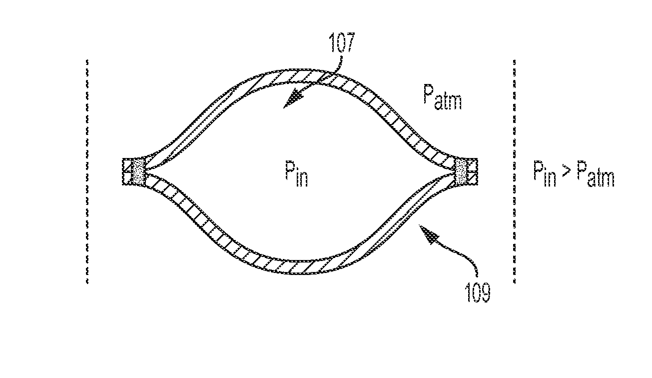
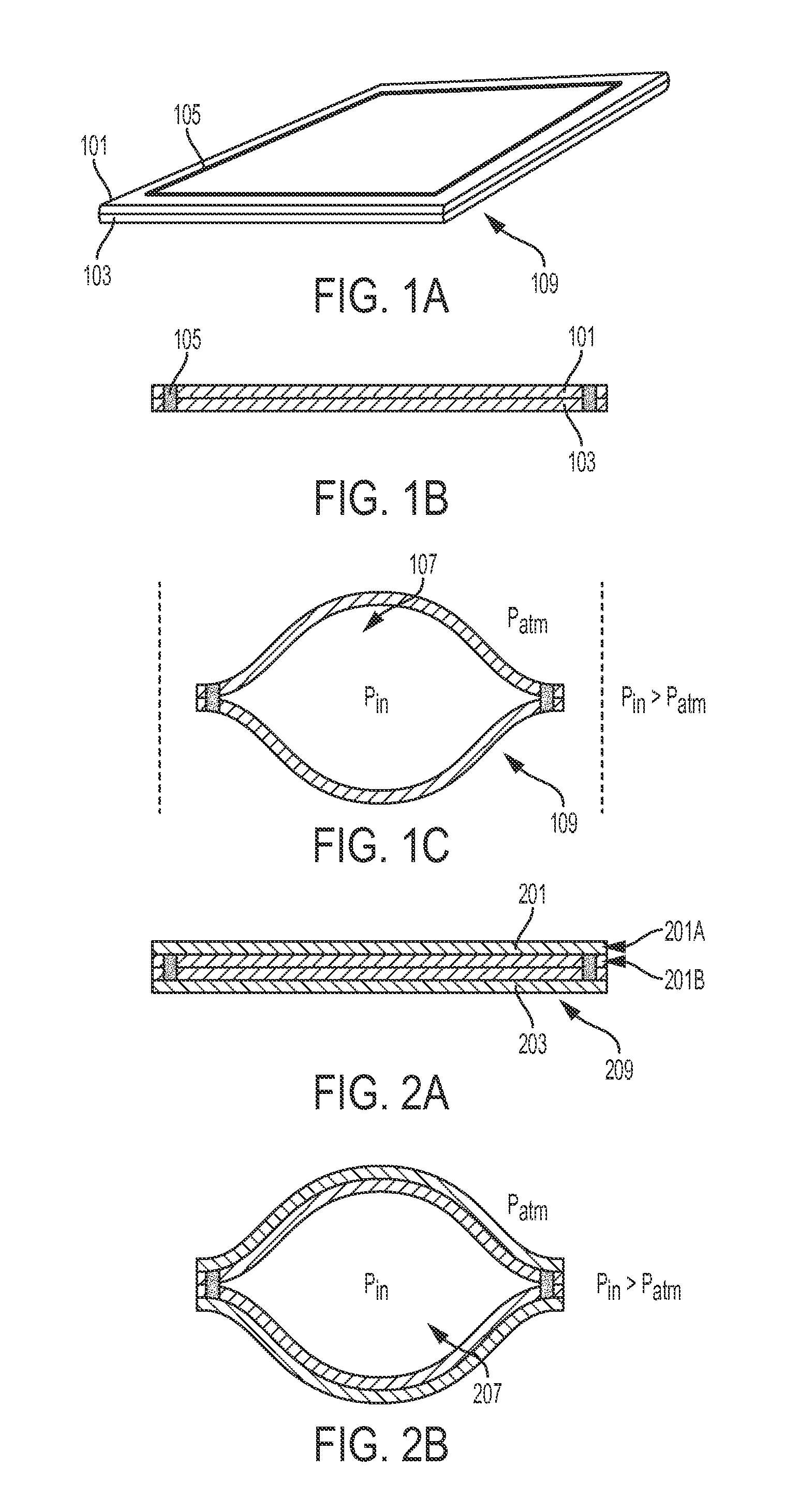
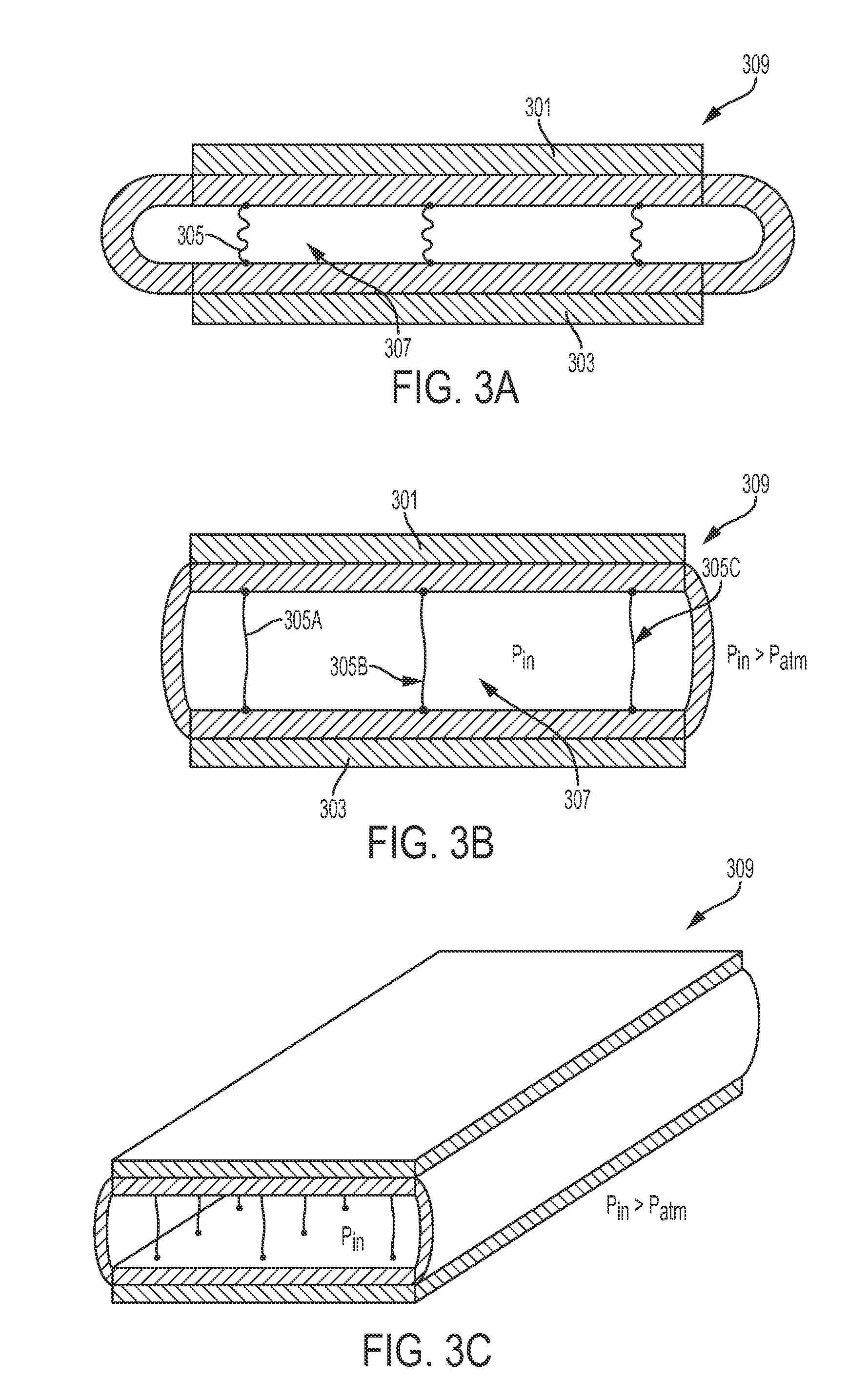
The patent describes a composite structural element that can be strengthened and made stiffer in its activated state. This is achieved by using an inflatable bladder or balloon to space apart flexible layers. The increased distance between the layers when the bladder is inflated increases the structural stiffness. Additionally, the patent also discusses how changing the effective thickness of a beam can impact its stiffness, either by adding multiple layers or through adhesion. Finally, the patent mentions that the distance between the first and second layers increases when the bladder is pressurized.

Problems solved by technology

This dramatically changes the stiffness of the beam.

Method used


Image

  • Rigidized Inflatable Structures
  • Rigidized Inflatable Structures
  • Rigidized Inflatable Structures

Examples


Embodiment Construction

[0096]The present disclosure identifies several techniques for altering the second moment of area of a structure in order to affect the overall stiffness of a structural element including flexible laminate material layers. “Second moment of area,” as used herein, is a measure of the ‘efficiency’ of a shape to resist bending caused by loading where a shape with a higher second of moment is more resistant to bending. The stiffness of a beam, k, is proportional to the product of the Young's modulus of the material, E, and the second moment of area, I. That is k∝EI. The second moment of area of a beam with a rectangular cross section is calculated at I=1 / 2bh3, where b is the width, and h is the thickness. Curving the cross section of the beam to form an arc shape can significantly increase the I value and therefore increase the stiffness of the beam (or its resistance to bending). For example, a beam that has a height of 0.0625″ and a width of 2″ has an I value of 2.4×10⁻⁴ inches4. Howe...


PUM

PropertyMeasurementUnit
three point bending testaaaaaaaaaa
thicknessaaaaaaaaaa
thicknessaaaaaaaaaa

Abstract

A composite structural element is described, including: a first laminate layer comprising a plurality of first material layers; a second laminate layer comprising a plurality of second material layers; and an inflatable bladder configured for connection with a fluid inflation or deflation source and disposed in-between the first and second laminate layers.

Description

RELATED APPLICATION[0001]The present application claims priority to U.S. Provisional Application 61 / 980,674, filed Apr. 17, 2014, the contents of which are hereby incorporated by reference herein in their entirety.GOVERNMENT FUNDING CLAUSE[0002]This invention was made with support from the United States government under Grant No. N66001-13-C-4036 awarded by DARPA. The United States government has certain rights to this invention.INCORPORATION BY REFERENCE[0003]All patents, patent applications and publications cited herein are hereby incorporated by reference in their entirety in order to more fully describe the state of the art as known to those skilled therein as of the date of the invention described herein.BACKGROUNDField of the Invention[0004]The present disclosure generally relates to the field of rigidized structures. In particular, the disclosure relates to structures that are flexible in their inactive state, and stiffen when activated. Structures that are permanently rigid—...

Claims


Application Information

Patent Timeline
Patent Type & Authority Applications(United States)
IPC IPC(8): B32B15/08A61F5/01B32B27/40
CPCB32B15/08B32B27/40A61F5/0102A61F5/0106B32B2535/00A61F5/012B32B2307/581B32B2571/02A61F5/0118A61F13/04
Inventor GALLOWAY, KEVIN C.KNOPF, RYANLESSING, JOSHUA AARON
Owner PRESIDENT & FELLOWS OF HARVARD COLLEGE
Learn More