Upshift shudder mitigation through clutch manipulation

a technology of clutch manipulation and transmission, which is applied in the direction of mechanical equipment, transportation and packaging, and gearing, etc., can solve the problems of increasing the tendency to shift shudder in the transmission, and achieve the effects of improving performance, less noticeable shudder, and increasing frequency

Active Publication Date: 2017-12-21
GM GLOBAL TECH OPERATIONS LLC
View PDF0 Cites 0 Cited by
  • Summary
  • Abstract
  • Description
  • Claims
  • Application Information

AI Technical Summary

Benefits of technology

The present disclosure provides a system and method for shifting a transmission in a vehicle transmission that reduces shudder and improves the overall performance of the transmission. The system includes multiple torque transmitting mechanisms that can be selectively engaged to interconnect the members of the transmission. The method includes applying the first torque transmitting mechanism to interconnect the first and second members of the transmission, and then disengaging the second torque transmitting mechanism. The second torque transmitting mechanism is then applied to interconnect the third and fourth members of the transmission, and the third torque transmitting mechanism is simultaneously kept applied to interconnect the third and fourth members. The method also includes disengaging the first torque transmitting mechanism and applying the second torque transmitting mechanism in a higher gear state if the vehicle speed is below a predetermined threshold. The control system includes multiple control logics that work together to select the appropriate torque transmitting mechanism and engage or disengage them in a timely manner to improve the performance of the transmission.

Problems solved by technology

However, providing more forward gear states has increased tendency toward shift shudder in the transmissions.

Method used


Image

  • Upshift shudder mitigation through clutch manipulation
  • Upshift shudder mitigation through clutch manipulation
  • Upshift shudder mitigation through clutch manipulation

Examples


Embodiment Construction

[0019]The following description is merely exemplary in nature and is not intended to limit the present disclosure, application, or uses.

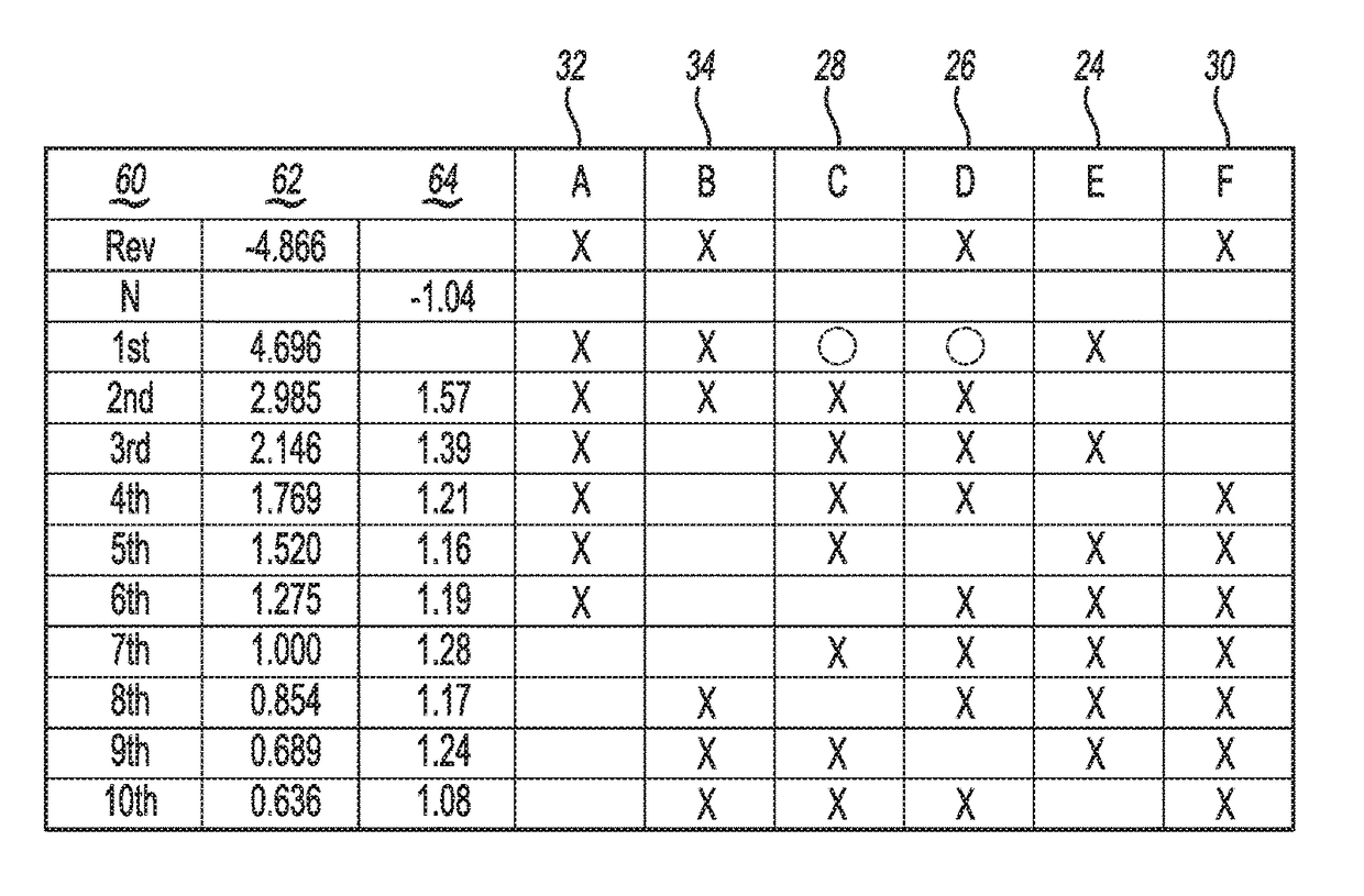
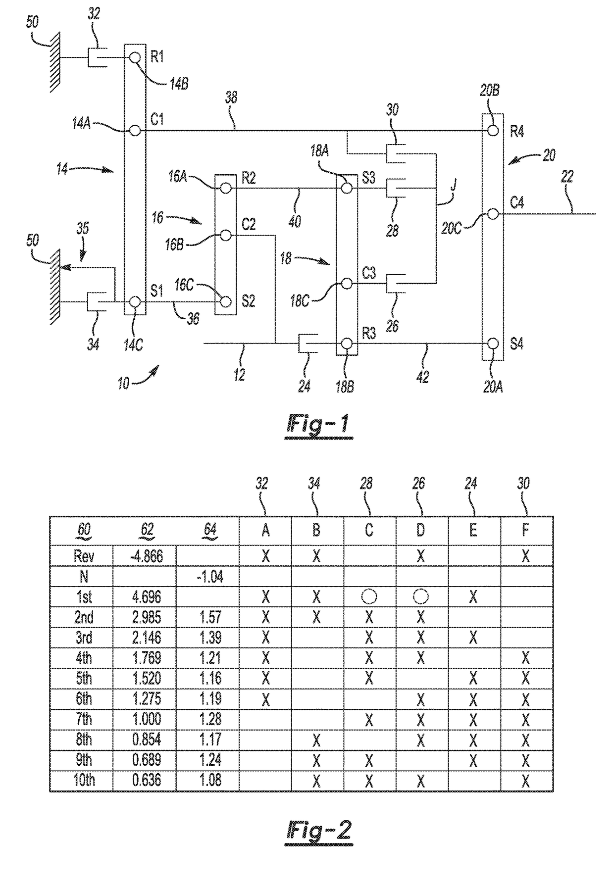
[0020]In some forms of the present disclosure, a nine, ten, or eleven speed transmission is provided, by way of example, in a relatively small package by achieving nine, ten, or eleven forward speeds with four planetary gear sets, two brakes, and four clutches. In other variations, however, additional brakes, clutches, planetary gear sets, or other components may be added, or deleted, and the disclosed subject matter may be used in transmissions with lower or higher number of gear states.

[0021]The automatic transmission illustrated herein has an arrangement of permanent mechanical connections between the elements of the four planetary gear sets. As used herein, coupling or interconnection refers to a direct, continuous, and permanent coupling or interconnection, for example by a rigid member or shaft, between elements. Selective coupling or intercon...


PUM


Abstract

A method and system are provided for shifting a vehicle transmission having several members. Each member is a first, second, or third node of a planetary gear set (of multiple planetary gear sets), or an input, output, or stationary member. A first torque transmitting mechanism is applied to transfer torque between first and second members in a low gear state. In some versions, a second torque transmitting mechanism is applied in the low gear state without substantially transferring torque between third and fourth members, and then the second torque transmitting mechanism is disengaged. A third torque transmitting mechanism is then applied without substantially transferring torque between the third and fourth members in the low gear state. The transmission is upshifted by disengaging the first torque transmitting mechanism, keeping the third torque transmitting mechanism applied, and applying the second torque transmitting mechanism to transfer torque between the third and fourth members.

Description

CROSS-REFERENCES TO RELATED APPLICATIONS[0001]This application claims the benefit of U.S. Provisional Patent Application No. 62 / 351,838, filed on Jun. 17, 2016, which is hereby incorporated by reference in its entirety.FIELD[0002]The invention relates generally to a system and method of shifting a multiple speed transmission, and more particularly to a method for shifting a transmission having a plurality of planetary gear sets and a plurality of torque transmitting devices.INTRODUCTION[0003]The statements in this section merely provide background information related to the present disclosure and may or may not constitute prior art.[0004]A typical multiple speed transmission uses a combination of friction clutches, planetary gear arrangements, and fixed interconnections to achieve a plurality of gear ratios. The number and physical arrangement of the planetary gear sets, generally, are dictated by packaging, cost and desired speed ratios.[0005]A drive toward efficiency and better fu...

Claims


Application Information

Patent Timeline
Patent Type & Authority Applications(United States)
IPC IPC(8): F16H3/66F16H61/02
CPCF16H3/66F16H61/0204F16H2200/2046F16H2200/2012F16H2200/0069F16H3/62F16H59/14F16H2059/147F16H61/686F16H61/0437F16H2200/2066F16H2200/2082B60W30/20B60W30/19B60W10/115B60W2510/104
Inventor GUNDERSON, JOEL H.HORGAN, JEREMY V.LI, DONGXU
Owner GM GLOBAL TECH OPERATIONS LLC
Why Eureka
Try Eureka