Snap fastener
a technology of snap fasteners and snaps, applied in the field of snap fasteners, can solve the problems of limiting the selection of materials, and achieve the effects of reducing costs, speeding up delivery, and avoiding delay
- Summary
- Abstract
- Description
- Claims
- Application Information
AI Technical Summary
Benefits of technology
Problems solved by technology
Method used
Image

Examples
first embodiment
1-10.
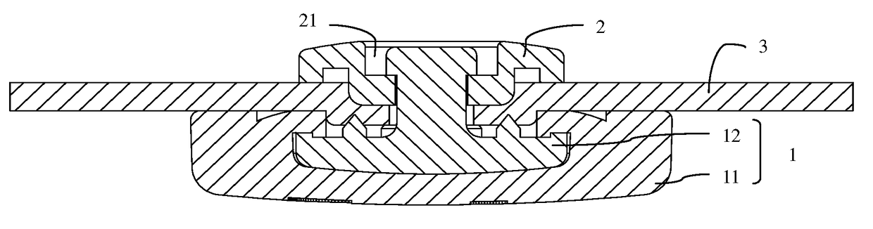
[0045]The FIG. 1 shows a snap fastener provided by the first preferred embodiment of the present application, and the snap fastener comprises a face fastener 1 and a locating fastener 2, which are snapped with each other. The locating fastener 2 can be a pin having a protruding rod structure as required, or can be a box having a recess structure, which is not specifically limited hereof.
[0046]In the embodiment, the face fastener 1 comprises a face shell 11 and a locating pin 12, which can be separable from each other. One end of the locating pin 12 is connected to the face shell 11, and the other end of the locating pin 12 passes through the substrate 3 and is connected to the locating fastener 2, so that the two sides of the substrate 3 are clamped by the face fastener 1 and the locating fastener 2 respectively. The substrate 3 can be made of fabric, plastic, leather, artificial leather or non-woven fabric, etc., and can usually be used for manufacturing bag bodies, shoe bodie...
second embodiment
b>11 and 12.
[0070]The face shell 11 of the present embodiment is made of plastic, and the difference between the present embodiment and the first embodiment lies at: the face shell 11 and the locating pin 12 in the present embodiment are assembled to form the face fastener 1 by way of heat-pressing as shown in FIGS. 11 and 12.
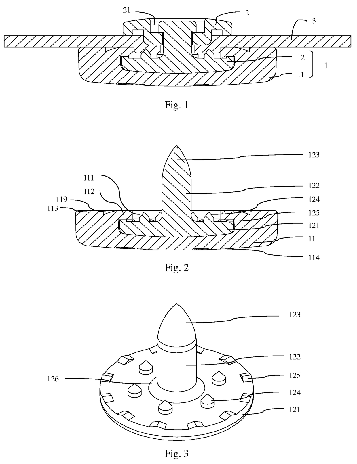
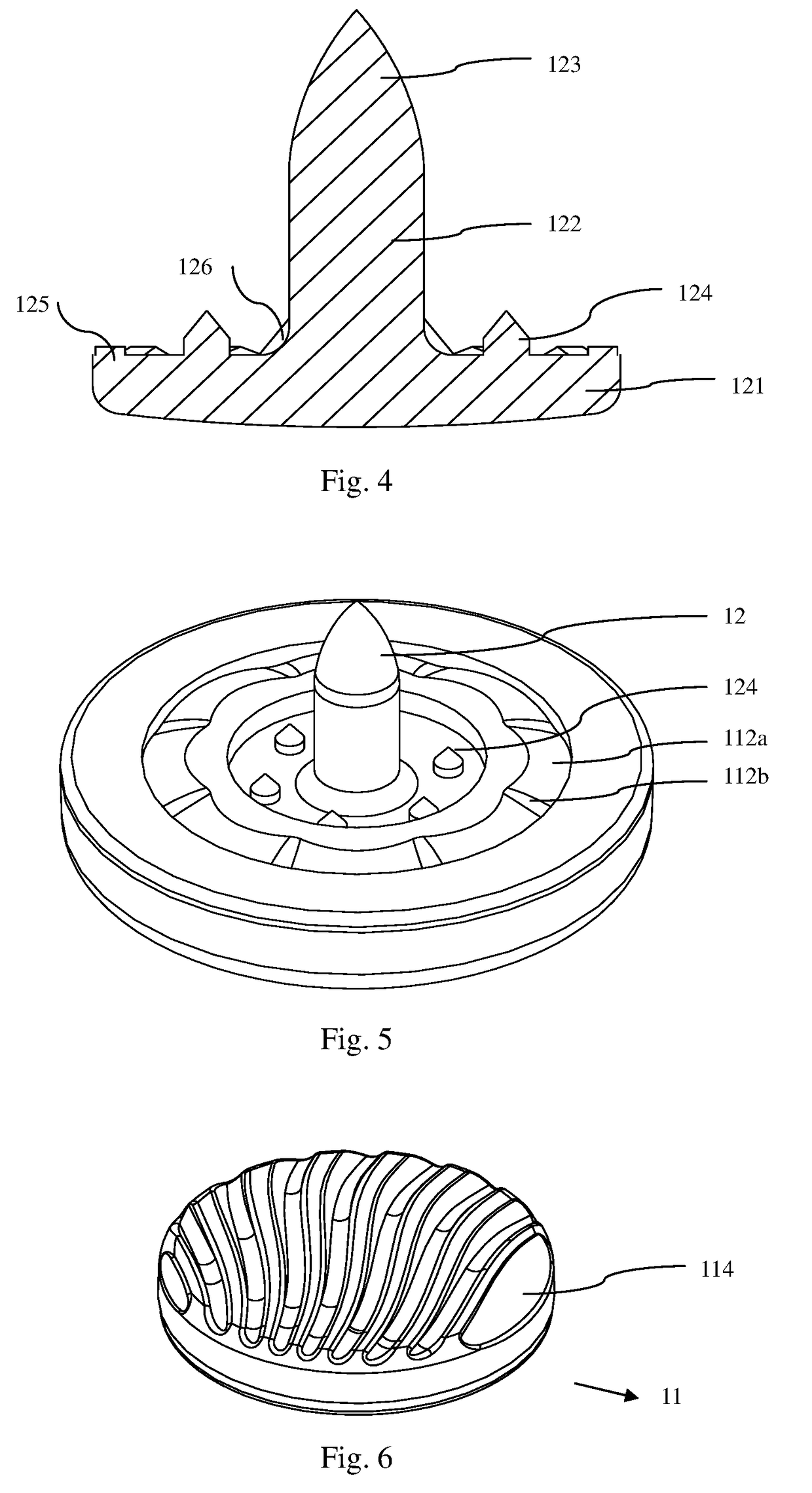
[0071]When assembled, the base 121 of the locating pin 12 is inserted down in the installation chamber 111 firstly, and abuts against the bottom of the installation chamber 111; and then, through heat-pressing, the fixing flange 112 is deformed thermally, and is bent towards the rod body 122 to cover the anti-rotation protrusions 125 completely; and the inner surfaces of the fixing flange 112 are arranged around the anti-rotation protrusions 125 to form concavo-convex occlusion, so that the disc-shaped fixing flange 112 abuts against the base 121 of the locating pin 12. The fixing flange 112 fits and abuts against the anti-rotation protrusions 125 to prevent th...
third embodiment
13-14.
[0074]The difference between the present embodiment and the aforementioned embodiment is: the face shell 11 of the present embodiment is formed out of the locating pin 12 directly by way of injection molding.
[0075]When assembled, the manufactured locating pin 12 is arranged in an injection mold; by way of the injection molding, the face shell 11 covers the base 121 of the locating pin 12 directly; and the injection molded face shell 11 completely covers the anti-rotation protrusions 125 and is meshed therewith to prevent the locating pin 12 from moving or rotating in the face shell 11; and the anti-skidding structures 124 and the rod body 122, located at the center of the end face of the base 121 are exposed out of the installation chamber 111 to prevent the face fastener 1 from sliding relative to the substrate 3.
[0076]Because the face shell 11 is a concave-convex structure formed directly by way of injection molding and meshed with the locating pin 12, the fixing flange 112 ...
PUM
 Abstract
Description
Claims
Application Information
 - R&D
- Intellectual Property
- Life Sciences
- Materials
- Tech Scout
- Unparalleled Data Quality
- Higher Quality Content
- 60% Fewer Hallucinations
Browse by: Latest US Patents, China's latest patents, Technical Efficacy Thesaurus, Application Domain, Technology Topic, Popular Technical Reports.
© 2025 PatSnap. All rights reserved.Legal|Privacy policy|Modern Slavery Act Transparency Statement|Sitemap|About US| Contact US: help@patsnap.com