Power supply management system

a management system and power supply technology, applied in the direction of computer control, process and machine control, instruments, etc., can solve the problems of excessive power consumption, high power consumption, and use of high power consumption time slots, so as to prevent the total amount of excess solar power, the power generation capacity of solar power generation devices can be effectively utilized, and the effect of inexpensive electrical energy

Active Publication Date: 2017-11-30
TOYOTA JIDOSHA KK
View PDF13 Cites 10 Cited by
  • Summary
  • Abstract
  • Description
  • Claims
  • Application Information

AI Technical Summary

Benefits of technology

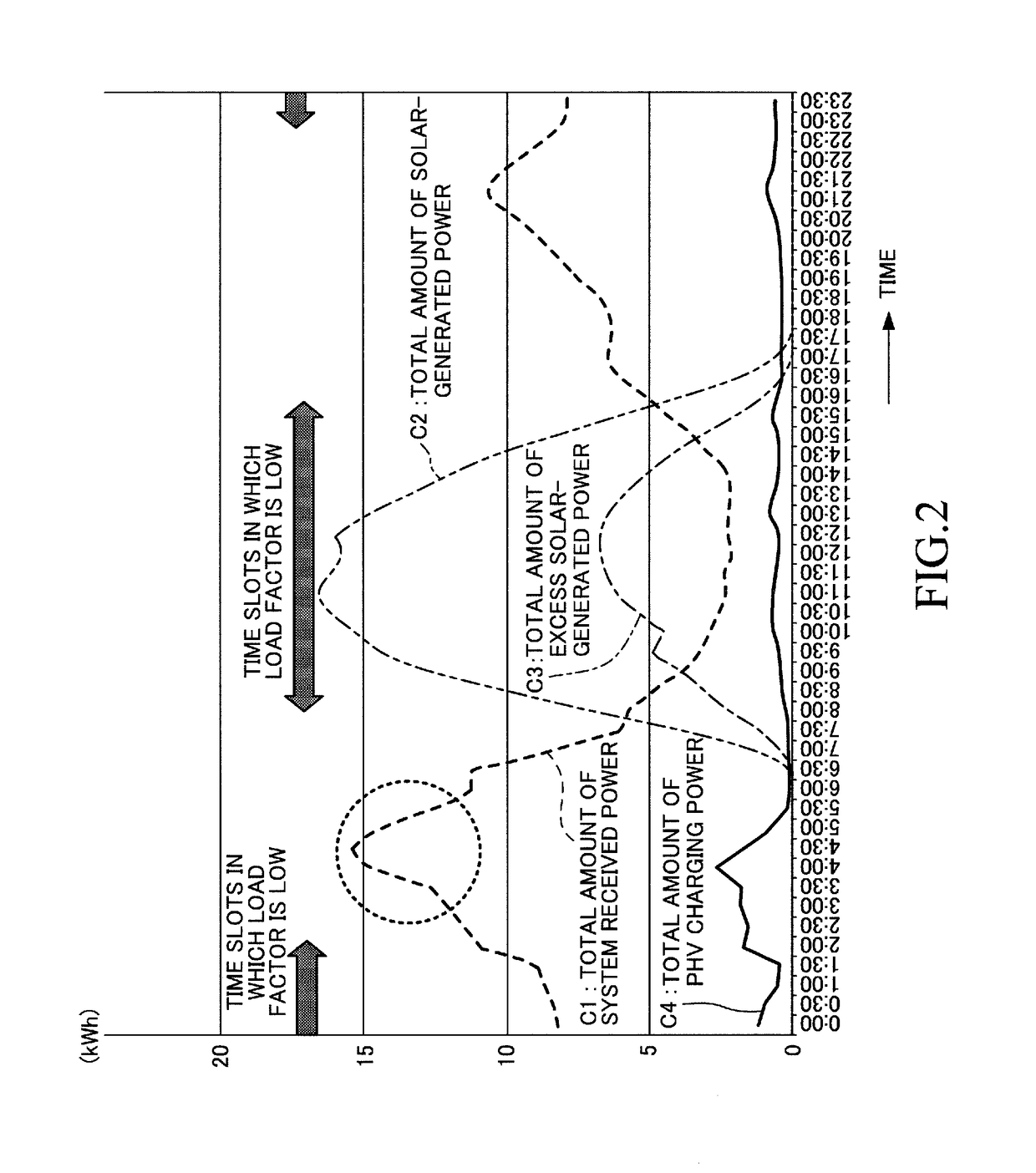
[0037]In order to address this problem, as in the above-mentioned aspect, when the predicted total amount of excess solar-generated power for the each time slot is equal to or more than “the amount of reverse flow suppression threshold power, which is determined on the basis of the rated capacity of the single transformer”, the second power fee unit price may be set to the lower limit value so that there is an increased possibility for the consumer to perform the power consumption behavior using the second electrical load device (for example, the charging of the vehicle-mounted storage battery). Therefore, the total amount of excess solar-generated power can be prevented from exceeding the amount of reverse flow suppression threshold power. As a result, the power generation by the solar power generation device is not suppressed so that the power generation capacity of the solar power generation device can be effectively utilized, and further, the consumer can obtain inexpensive electrical energy in place of, for example, gasoline.

Problems solved by technology

Further, in the residence of the consumer, there is often a load (hereinafter also referred to as “high power consumption load”) with extremely high power consumption as compared to the household electrical loads, for example, a charge / discharge device configured to charge a vehicle-mounted storage battery of a plug-in hybrid vehicle or electric vehicle, etc.
However, it is often the case that a time slot in which the consumer uses the high power consumption load, for example, the PHV / EV etc.
In other words, the time slot in which the high power consumption load is used (for example, the time slot in which the vehicle-mounted storage battery is charged in the residence of the consumer) is often restricted.
As a result, there is a problem that it is not easy to more appropriately level the amount of power consumption.

Method used


Image

  • Power supply management system
  • Power supply management system
  • Power supply management system

Examples


Embodiment Construction

[0045](Configuration of System)

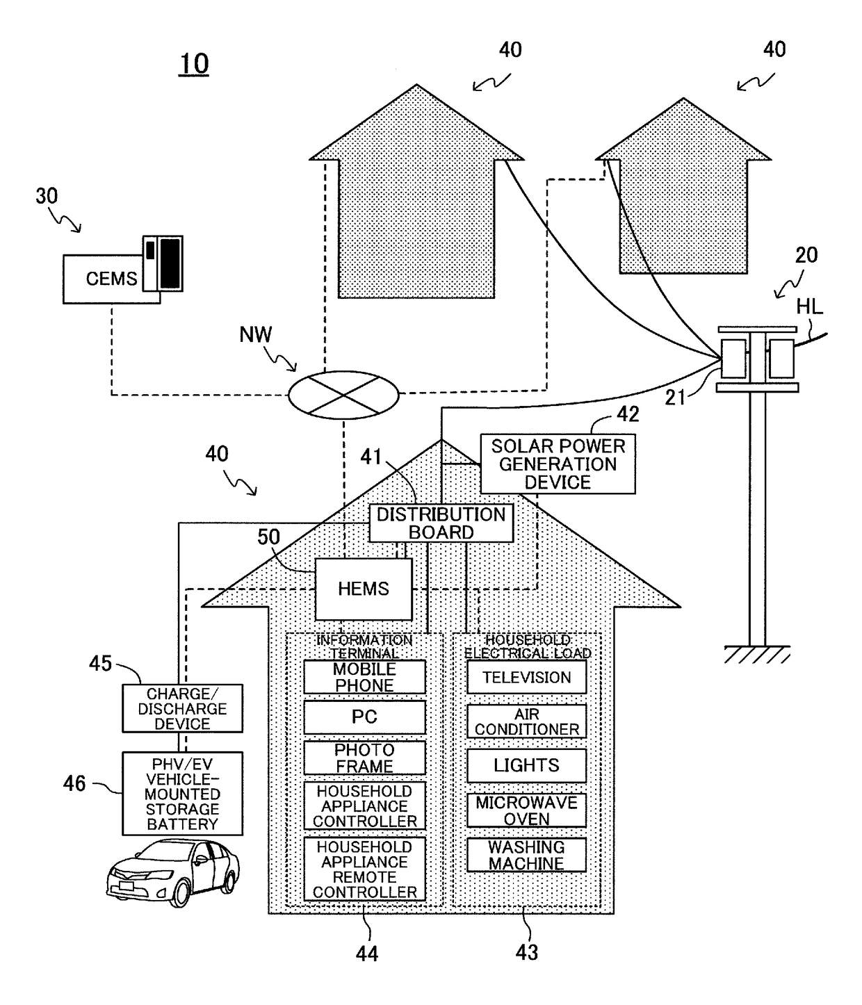
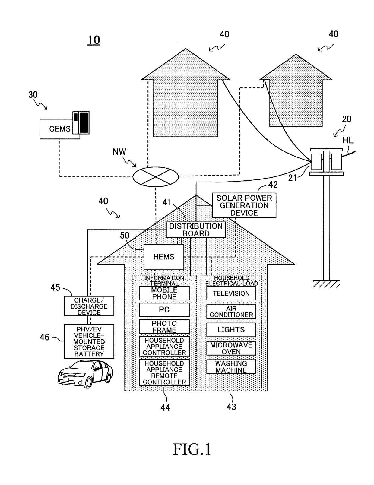
[0046]In FIG. 1, a schematic configuration of a power supply management system (hereinafter also referred to as “this system”) 10 according to an embodiment of the present invention is illustrated. This system 10 also serves as a power fee-related information provision system configured to notify a consumer of information on a power fee unit price. This system 10 includes a commercial power supply system 20, a community energy management system (CEMS) 30, and residences 40 of a plurality of consumers (individual users of electric power). In FIG. 1, the solid line indicates an electric power line, and the broken line indicates a data communication line.

[0047]The commercial power supply / source system (power supply system) 20 is a system configured to transmit electric power generated in a power plant (for example, thermal power plant) of an electric power supplier (electric power company) to “the residences 40 and unillustrated user facilities, such as a...


PUM


Abstract

A power supply management system according to an embodiment of the present invention includes a fee setting unit configured to set power fee unit prices (first power fee unit price and second power fee unit price for each time slot, and a notification unit configured to notify a consumer of information on the set power fee unit prices. The first power fee unit price is a power unit price for a household electrical load, and the second power fee unit price is a power unit price in a case of using a charge/discharge device to charge a vehicle-mounted storage battery. The fee setting unit is configured to set, by predicting a load factor of a transformer, a discount rate of the second power fee unit price to become higher (second power fee unit price to become lower) as the predicted load factor becomes lower. The second power fee unit price is determined on the basis of the first power fee unit price and the discount rate.

Description

TECHNICAL FIELD[0001]The present invention relates to a power supply management system, which is capable of providing information on at least an electricity fee to a consumer of electric power.BACKGROUND ART[0002]There has been known, as the related art, an apparatus configured to receive information on an electricity fee (power fee unit price) for each time slot from the outside, and to notify a consumer (user) of the received information on the electricity fee for each time slot (see, for example, Patent Literature 1).[0003]In general, in order to level a proportion of an amount of power consumption (amount of demand power) to an amount of generated power (amount of suppliable power), an electricity fee is set at a low fee in a time slot in which the amount of power consumption is small with respect to the amount of generated power (that is, time slot with a sufficient amount of suppliable power). Further, the consumer generally tends to behave so as to use an electrical load devi...

Claims


Application Information

Patent Timeline
Patent Type & Authority Applications(United States)
IPC IPC(8): G06Q50/06G05B15/02H02J3/14H02J3/38G06Q30/04B60L11/18H02J3/00H02J7/35
CPCG06Q50/06G05B15/02H02J3/14H02J3/383H02J7/35H02J2003/143B60L11/1809H02J2003/003G06Q30/04Y02B70/3225Y04S20/222Y04S50/12B60L53/00H02J2310/14H02J3/003H02J2300/24H02J3/381B60L53/51Y02B10/10Y02E10/56Y02T10/70Y02T90/12Y02T10/7072Y04S20/242Y02B70/30H02J2310/64H02J3/38
Inventor HIRATA, TETSUYAKAWAMOTO, MASAYUKIKOREISHI, JUNMORII, TATSUYAITO, KOSHIMATSUNAGA, KENGOYAMADA, TAKAHIRO
Owner TOYOTA JIDOSHA KK
Why Eureka
Try Eureka