Hand-held Voltmeter for Electric Fence
a voltmeter and electric fence technology, applied in the field of voltmeters, can solve the problems of weak current flowing through the animal, weak current flowing through the fence, and electric fence experiencing unwanted low voltage on the fence wire, etc., to achieve accurate measurement of the peak voltage of the electric fence, convenient use, and quick measurement
- Summary
- Abstract
- Description
- Claims
- Application Information
AI Technical Summary
Benefits of technology
Problems solved by technology
Method used
Image
Examples
first embodiment
[0050]Now, the present disclosure which reflects the aforementioned design considerations will be described in detail.
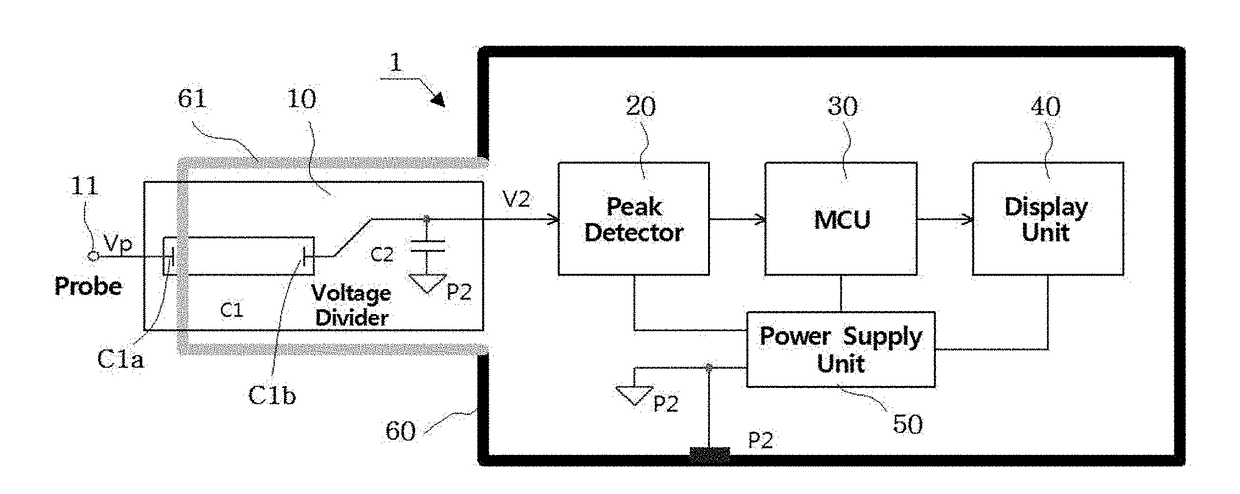
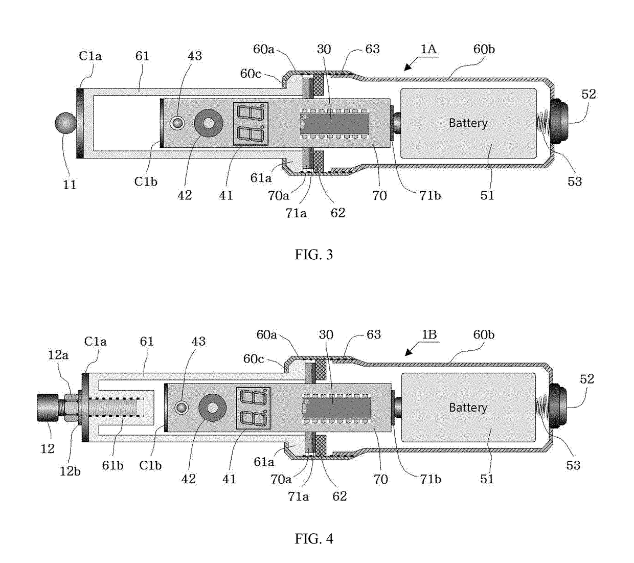
[0051]Referring to FIG. 3, in the first embodiment, the electric fence voltmeter 1A includes:
[0052]a cylindrical body case 60 of which one side has an opening;
[0053]a cylindrical sensor case 61 connected to the opening of the body case 60 to protrude from the body case 60;
[0054]a printed circuit board 70 in which a part of the voltage divider 10, the peak detector 20, the MCU 30, the display unit 40, and other electronic parts are assembled; and
[0055]a power supply unit 50 for supplying electric power to the elements constituting the voltmeter.
[0056]The capacitor C1 of the voltage divider 10 has the first electrode C1a placed on the outer end of the sensor case 61 in the form of a surface electrode, and the second electrode C1b placed in the inside of the sensor case 61 in the form of a surface electrode that is spaced oppositely to the first electrode C1a at a prede...
second embodiment
[0067]Meanwhile, referring to FIG. 4, in the present discloser, the voltmeter 1B has a means for adjusting the capacitance of the capacitor C1 to set up the voltage division ratio (Rd). The capacitance of the capacitor C1 can be adjusted by modulating the equivalent distance between the first electrode C1a and the second electrode C1b of the capacitor C1.
[0068]That is, in the second embodiment, the electric fence voltmeter 1B further includes:
[0069]a bolt shaped capacitance adjuster 12 made of a conductive material screwed through a hole formed at the center of the first electrode C1a of the capacitor C1 into a threaded blind hole 61b formed inside of the sensor case 61 directed to the second electrode C1b; and
[0070]a locking means 12a for locking the screw coupling of the capacitance adjuster 12 and the threaded blind hole 61b at an arbitrary position,
[0071]on the electric fence voltmeter 1A.
[0072]The head of the bolt shaped capacitance adjuster 12 may also be used as the probe 11 ...
PUM
 Abstract
Description
Claims
Application Information
 - R&D
- Intellectual Property
- Life Sciences
- Materials
- Tech Scout
- Unparalleled Data Quality
- Higher Quality Content
- 60% Fewer Hallucinations
Browse by: Latest US Patents, China's latest patents, Technical Efficacy Thesaurus, Application Domain, Technology Topic, Popular Technical Reports.
© 2025 PatSnap. All rights reserved.Legal|Privacy policy|Modern Slavery Act Transparency Statement|Sitemap|About US| Contact US: help@patsnap.com


