Flow path joint and liquid ejecting apparatus
a flow path and liquid ejecting technology, applied in the direction of pipe joints, sleeves/socket joints, printing, etc., can solve the problem of absorbing position errors between the first flow path and the second flow path, and achieve the effect of suppressing air bubble retention
- Summary
- Abstract
- Description
- Claims
- Application Information
AI Technical Summary
Benefits of technology
Problems solved by technology
Method used
Image
Examples
first embodiment
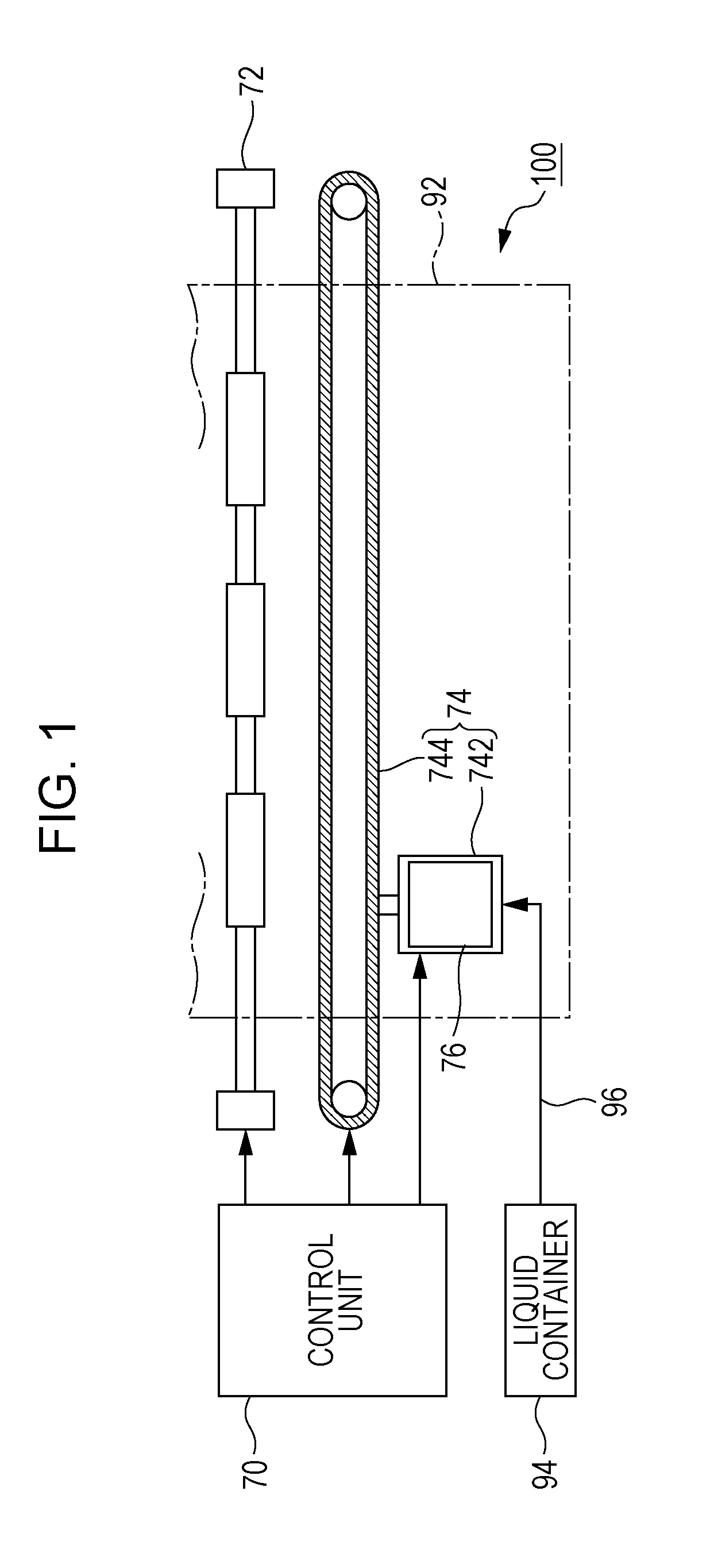
[0026]FIG. 1 is a schematic view that exemplifies a liquid ejecting apparatus 100 according to a first embodiment of the invention. The liquid ejecting apparatus 100 in the first embodiment is an ink jet type printing apparatus that ejects ink that is an example of liquid on a medium 92. The medium 92 is typically printing paper, and an arbitrary target for printing such as a resin film or a cloth may be used as the medium 92. As exemplified in FIG. 1, a liquid container 94 which retains ink is mounted in the liquid ejecting apparatus 100. For example, it is possible to use a cartridge that is attachable to and detachable from the liquid ejecting apparatus 100, a bag shape ink pack that is formed by a flexible film, or an ink tank that is able to replenish ink as the liquid container 94. A plurality of types of ink that have different colors are retained in the liquid container 94, and are supplied to a liquid ejecting head 76 via a supply pipe 96.
[0027]As exemplified in FIG. 1, the...
second embodiment
[0049]A second embodiment of the invention will be described. Note that, in each of the aspects exemplified below, concerning components which have the same actions and functions as the first embodiment, detailed explanation will be omitted as appropriate by using the same reference numerals which are explained in the first embodiment.
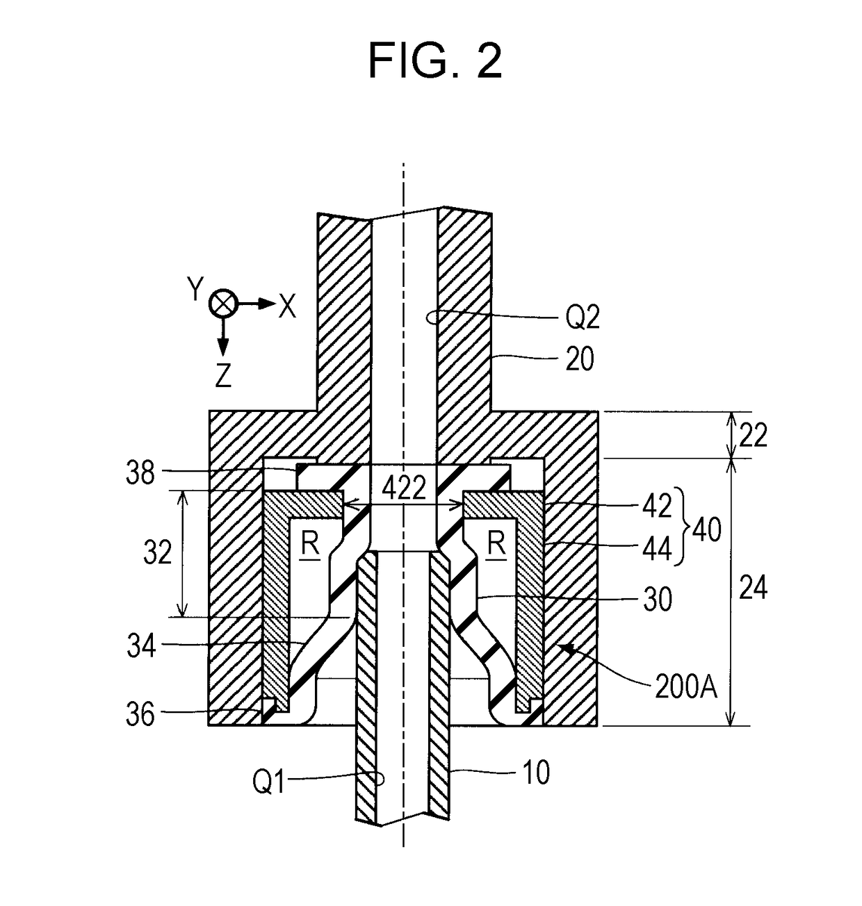
[0050]FIG. 6 is a sectional view of a flow path joint 200B in the second embodiment. A state prior to press fitting of the tubular body 10 with respect to the elastic member 30 is exemplified in FIG. 6. As exemplified in FIG. 6, the elastic member 30 of the second embodiment is equipped with a pipe internal projecting portion 322 that is added to elements that are similar to in the first embodiment. The pipe internal projecting portion 322 is a projection that is formed on the inner wall surface of the press fitting portion 32. The pipe internal projecting portion 322 in the first embodiment is formed in an annular shape along a peripheral direction of...
third embodiment
[0055]FIG. 8 is a sectional view in a third embodiment. In the third embodiment, the flow path joint 200A is used in the same manner as in the first embodiment. As exemplified in FIG. 8, a flange portion (flange) 12 is formed on the tubular body 10 in the third embodiment. The flange portion 12 is an annular plate shape part that protrudes from the outer wall surface of the tubular body 10 in a direction that is parallel to the X-Y plane. The external form of the flange portion 12 is larger than the outer diameter of the holding portion 36 out of the elastic member 30. In detail, the outer diameter of the flange portion 12 is substantially equal to the outer diameter of the accommodating portion 24 of the flow path member 20. As exemplified in FIG. 8, the front surface on the negative side in the Z direction out of the flange portion 12 abuts with the end surface on the positive side in the Z direction out of the accommodating portion 24 of the flow path member 20 and the front surf...
PUM
 Abstract
Description
Claims
Application Information
 - R&D
- Intellectual Property
- Life Sciences
- Materials
- Tech Scout
- Unparalleled Data Quality
- Higher Quality Content
- 60% Fewer Hallucinations
Browse by: Latest US Patents, China's latest patents, Technical Efficacy Thesaurus, Application Domain, Technology Topic, Popular Technical Reports.
© 2025 PatSnap. All rights reserved.Legal|Privacy policy|Modern Slavery Act Transparency Statement|Sitemap|About US| Contact US: help@patsnap.com


