
Image display apparatus allowing operation of image screen and operation method thereof

a technology of image display and operation method, which is applied in the direction of instruments, computing, electric digital data processing, etc., can solve the problems of insufficient improvement of the operation characteristic of the display screen, rather burdensome user, and very troublesome operation for the user, and achieves the effect of easy and intuitive operation

Inactive Publication Date: 2017-11-23
SHARP KK
View PDF3 Cites 0 Cited by
  • Summary
  • Abstract
  • Description
  • Claims
  • Application Information

AI Technical Summary

Benefits of technology

This solution simplifies and streamlines operations, allowing users to navigate page images intuitively, similar to turning paper pages, and reduces the burden of mode switching, enhancing user experience, especially in shared display environments.

Problems solved by technology

The operation characteristic of a display screen, however, is not sufficiently improved.
Such operations are very troublesome for the user.
In order to avoid such a situation, it is necessary for the user to be always aware of whether the display is in the drawing mode, or to confirm the mode before starting any operation, which is rather burdensome for the user.
Particularly when a large touch-panel display displaying an image is shared among a plurality of users discussing while operating the image screen, we cannot expect that every user correctly recognizes whether the operation is in the drawing mode or not and operates the image screen appropriately.
Further, it is troublesome to cancel and reset the drawing mode when only one window operation is to be done.
An image display apparatus having a function of drawing a pre-set figure or the like at a touched position has been known, and the same problem occurs in such an apparatus.
The technique disclosed in '491 Reference does not suppose an operation on a touch-panel display of a large size, and the problem described above that occurs when the window is operated on the large-size touch-panel display cannot be solved.

Method used


Image

  • Image display apparatus allowing operation of image screen and operation method thereof
  • Image display apparatus allowing operation of image screen and operation method thereof
  • Image display apparatus allowing operation of image screen and operation method thereof

Examples


Embodiment Construction

[0034]In the embodiment below, the same components are denoted by the same reference characters. Their names and functions are also the same. Therefore, detailed description thereof will not be repeated.

[0035]In the following, “touch” means a state in which a detecting device for detecting an input position can detect the position, and it includes a state (in which one's finger or the like is) in contact with and pressing the detecting device, a state in contact with but not pressing the detecting device, and a state not in contact but in the vicinity of the detecting device. As will be described later, as the detecting device for detecting an input position, a contact type as well as non-contact type device may be used. When a non-contact type detecting device is used, “touch” means that one's finger or the like comes to a distance to the detecting device close enough for the device to detect the input position.

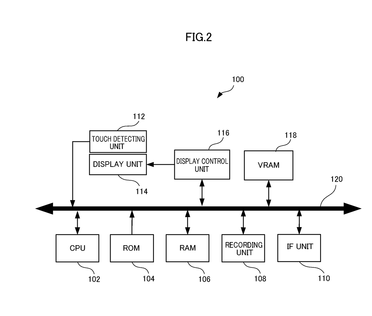
[0036]Referring to FIG. 2, an image display apparatus 100 in accordance...


PUM


Abstract

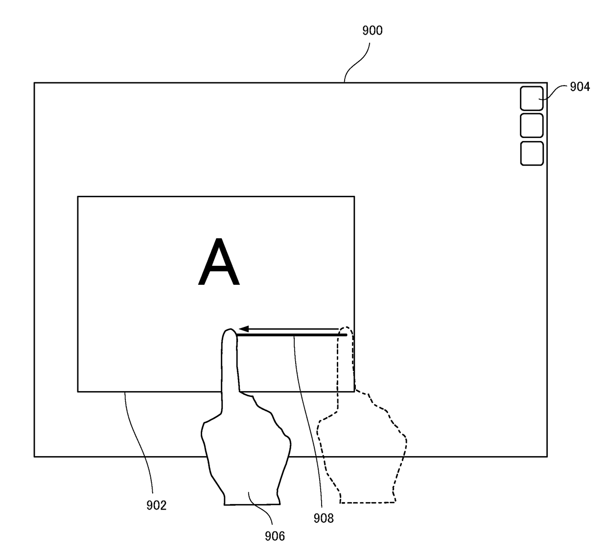
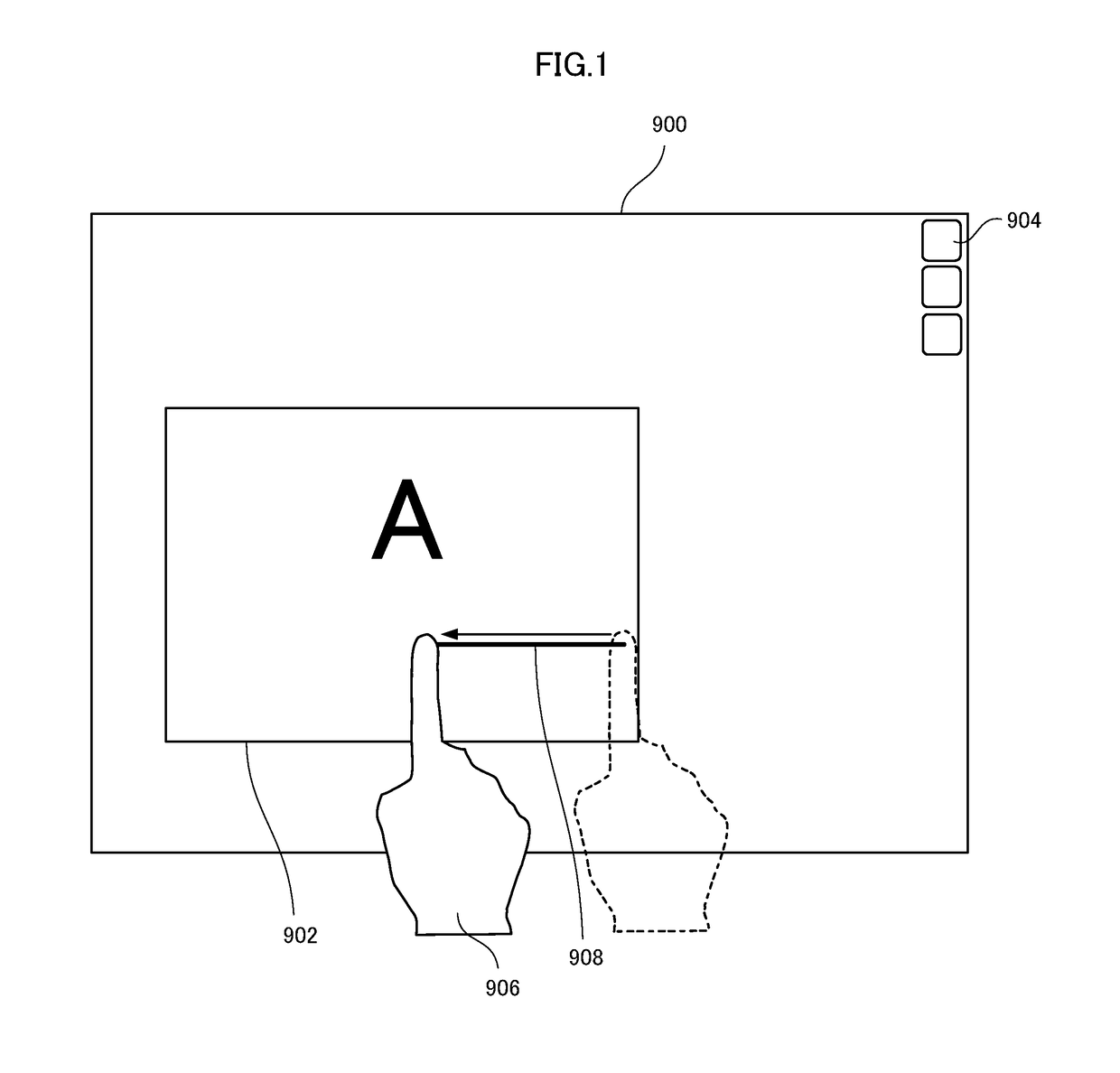
An image display apparatus includes a display unit for displaying an image, a detecting unit for detecting a position designated by an operation of designating a position on the displayed image and a file operation unit operating a file. The display unit displays images generated from a file on page-by-page basis on a partial area of the display unit. The file operating unit operates the file in accordance with the change of position detected by the detecting unit, when, in a state in which no position has been detected by the detecting unit, a designated position outside of the prescribed partial area is first detected by the detecting unit and the designated position changes while the position designating operation is maintained and then no position is detected by the detecting unit. Thus, the user can easily and intuitively operate the displayed page image or the file.

Description

CROSS-REFERENCE TO RELATED APPLICATIONS[0001]This nonprovisional application claims priority under 35 U.S.C. §119(a) on Patent Application No. 2013-130701 filed in Japan on Jun. 21, 2013, the entire contents of which are hereby incorporated by reference.BACKGROUND OF THE INVENTIONField of the Invention[0002]The present invention relates to an image display apparatus allowing operation of image screen that allows easy and intuitive operation of a page image displayed on a partial area of a display screen or operation of its file, as well as to a method of operating the same.Description of the Background Art[0003]In an image display apparatus such as an liquid crystal display, as a user interface for operating a window displayed on the display screen, a method of clicking buttons and icons displayed on the window or selecting from a pull-down menu to realize a prescribed process has been known. A mouse for a computer has been conventionally known as an operating device for this purpos...

Claims


Application Information

Patent Timeline
Patent Type & Authority Applications(United States)
IPC IPC(8): G06F3/0483G06F3/0488
CPCG06F3/04883G06F3/0483
Inventor OKIGAMI, MASAFUMITERADA, SATOSHI
Owner SHARP KK
Learn More