
Hot Air Nozzle and its Production Method

a technology of hot air nozzles and production methods, which is applied in the direction of air heaters, fluid heaters, lighting and heating apparatus, etc., can solve the problems of inadvertent heat transfer of conventional nozzles, complicated structure of conventional nozzles, and inability to achieve the effect of reducing the number of nozzles

Active Publication Date: 2017-11-23
HAKKO CO LTD
View PDF2 Cites 1 Cited by
  • Summary
  • Abstract
  • Description
  • Claims
  • Application Information

AI Technical Summary

Benefits of technology

The present invention is a design for a hot air nozzle that has a simple structure and is designed to protect against heat transfer to surrounding electrical components. The nozzle is designed to be mounted on the end of a heating device and provides a uniform temperature environment while suppressing local excess heating. It allows for effective and efficient heating of electrical components with minimal hot air exhaust. The nozzle is not complicated in its structure. Overall, the invention provides a simple and efficient solution for heating electrical components.

Problems solved by technology

However, when hot air is blown on a targeted electronic device directly, the thermal energy may be undesirably transmitted to other electronic elements adjoining the targeted device.
This inadvertent heat transfer occurs with contemporary nozzles because the nozzles are held above or floated over a substrate and the targeted device, and the hot air must exhaust via the space between the nozzle and the substrate.
When the user wants to prevent thermal energy from transferring heat undesirably to adjacent components from a space between the nozzle and the substrate, the conventional nozzles have complicated structures.
Conventional nozzles with complicated structures tend to be unsuitable for high density mounted PCB components due to their size.
Reducing the size of conventional nozzles with complicated structures is expensive.

Method used


Image

  • Hot Air Nozzle and its Production Method
  • Hot Air Nozzle and its Production Method
  • Hot Air Nozzle and its Production Method

Examples


Embodiment Construction

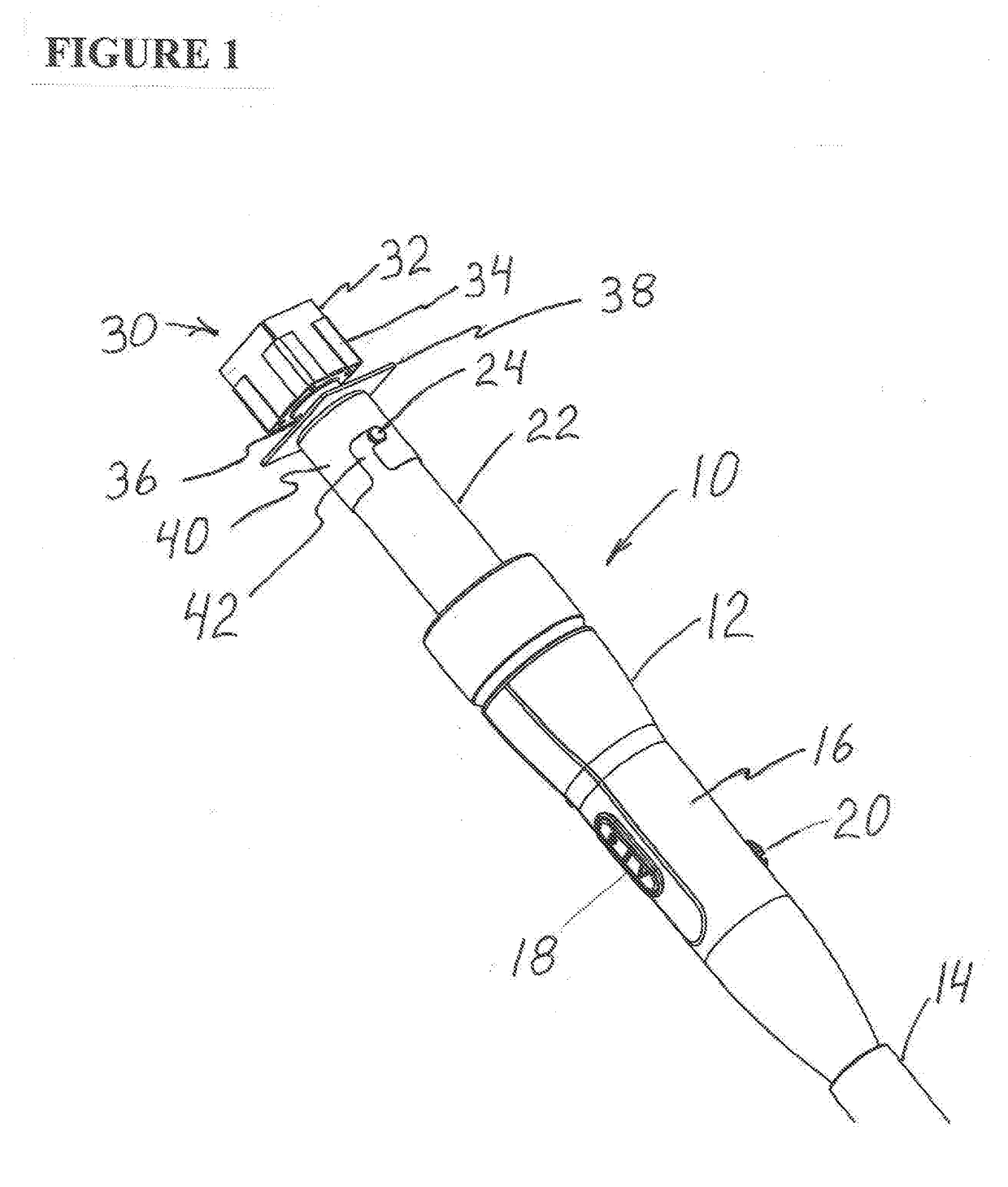
[0010]FIG. 1 shows a perspective view of an exemplary hand-piece portion of a hot air blower 10. The hot air blower 10 includes a handle section 12 connected at a proximal end to a cable 14 extending to a control box (not shown). The handle section 12 includes an insulated grip 16 as well as a switch 18 and control knob 20. Switch 18 controls the flow of air from the hot air blower 10. Control knob 20 may be used to control the application of a vacuum. The handle section 12 of the hot air blower 10 also includes a blowout cylinder 22 at the distal end, which encloses the heating element. The blowout cylinder is a metallic element having at least one projecting bump 24.

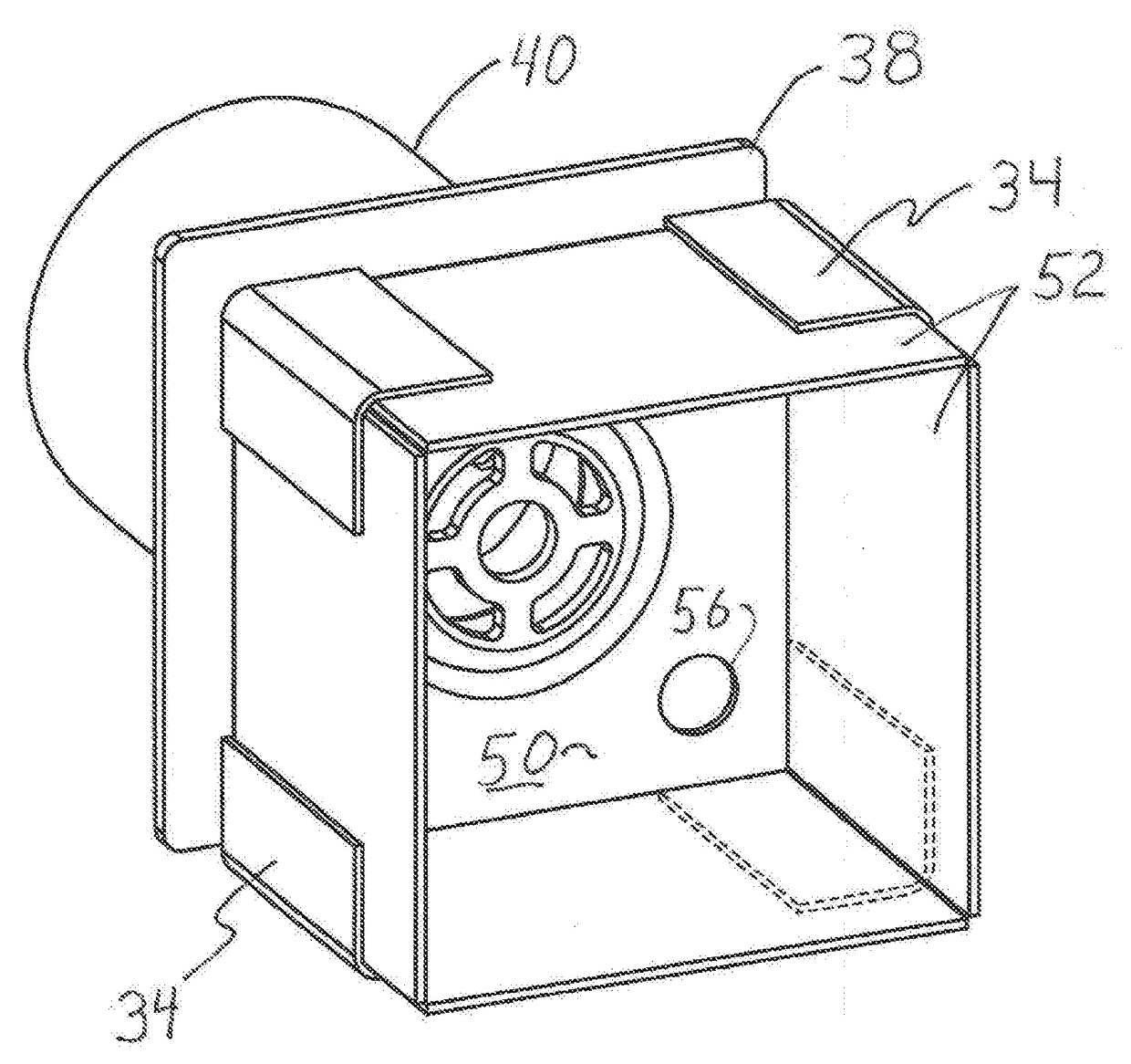
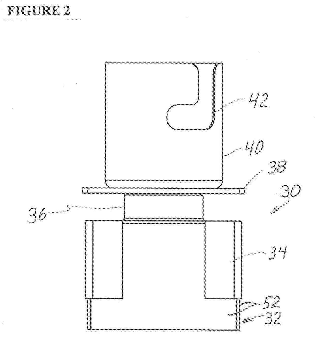
[0011]FIG. 1 also depicts the hot air nozzle 30 of the present invention secured to the distal end of the blowout cylinder 22 of the handle section 12 of the hot air blower 10. The hot air nozzle 30 comprises a convection box 32 having corner supports or brace plates 34. The convection box 32 is attached to and extends...


PUM


Abstract

The invention is directed to a nozzle for a hot air device used in the electronic assembly industry to melt solder or heat shrink-wrap insulators. The nozzle provides a uniform temperature environment and suppresses the occurrence of local excess heating.

Description

FIELD OF THE INVENTION[0001]The present invention relates to a nozzle for a hot air device used in the electronic assembly industry to melt solder or heat shrink-wrap insulators. The nozzle provides a uniform temperature environment and suppresses the occurrence of local excess heating.BACKGROUND OF THE INVENTION[0002]In the electronics fabrication and re-working field, a hot air device is often used to melt solder when a user is required to dismount or remove and replace an electrical component. Hot air may also be used to heat shrink-wrap insulation materials. However, when hot air is blown on a targeted electronic device directly, the thermal energy may be undesirably transmitted to other electronic elements adjoining the targeted device. This inadvertent heat transfer occurs with contemporary nozzles because the nozzles are held above or floated over a substrate and the targeted device, and the hot air must exhaust via the space between the nozzle and the substrate. When the use...

Claims


Application Information

Patent Timeline
Patent Type & Authority Applications(United States)
IPC IPC(8): F24H3/04
CPCF24H3/04
Inventor TERAOKA, YOSHITOMONEMOTO, HISAO
Owner HAKKO CO LTD
Learn More