
Electrical contact element, press-in pin, bushing, and leadframe

a contact element and press-in pin technology, applied in the direction of coupling contact members, coupling device connections, electrical equipment, etc., can solve the problems of affecting the service life of the component, the tendency of the coating to form whiskers, and the malfunction of the component, so as to achieve the lowest possible tendency for whisker growth and less inclined to grow whiskers

Inactive Publication Date: 2017-11-16
HERAEUS PRECIOUS METALS GMBH & CO KG
View PDF15 Cites 4 Cited by
  • Summary
  • Abstract
  • Description
  • Claims
  • Application Information

AI Technical Summary

Benefits of technology

The present invention aims to provide an electrical contact element that is less inclined to grow whiskers. It also looks to provide a press-in pin that is pressed into a bushing with a minimum likelihood of whisker growth. Additionally, the invention looks to develop a leadframe or stamped frame in a way that contacting recesses and through-going openings are less likely to grow whiskers. The invention's base body and inner layer of tin are very thin, which can cause whisker growth. However, when the contact element is compressed or contacted, the thin outer layer of silver can mechanically mix or mix through with the inner layer, resulting in significantly less whisker growth.

Problems solved by technology

Press-fit contacts are usually coated with tin or tin alloys, wherein it is known that coatings of this type have a tendency to form whiskers.
Although it is possible in the case of higher currents that whiskers burn through, it is still possible for the flowing current to cause damage to components and / or cause malfunctions within the component even before such a burn-through occurs.
Leaded materials of this type are however detrimental to health so that as far as possible leaded solder should not be used.

Method used


Image

  • Electrical contact element, press-in pin, bushing, and leadframe
  • Electrical contact element, press-in pin, bushing, and leadframe
  • Electrical contact element, press-in pin, bushing, and leadframe

Examples


Embodiment Construction

[0032]Identical reference numerals are used hereinunder for like and like-functioning parts.

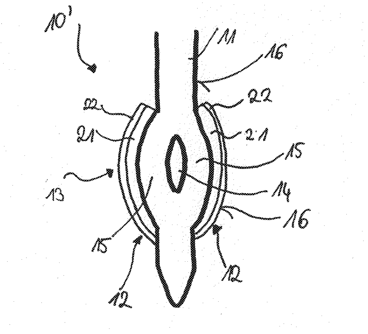
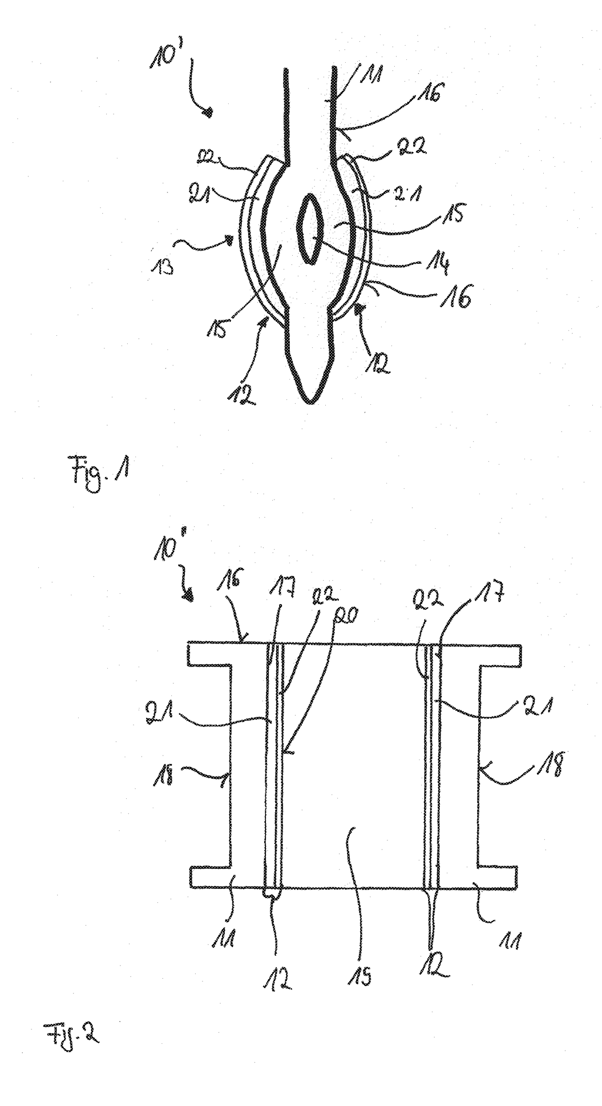
[0033]FIG. 1 illustrates an electrical contact element 10′ that is embodied as a press-in pin. The electrical contact element 10′ comprises a base body 11 having a press-in section 13 that is embodied in the form of two arms 15 that are separated by means of an intermediate space 14. The press-in section 13 is embodied in a flexible manner.

[0034]The base body 11 is covered in sections by a coating 12, wherein the coating 12 comprises an inner layer 21 and an outer layer 22. The inner layer 21 is applied to the base body 11 and the outer layer 22 is applied to the inner layer 21. The outer layer 22 of the coating 12 forms at least in sections a surface or portion of the surface 16 of the electrical contact element 10′. The illustrated thickness ratios of the coating 12 in relation to the base body 11 are provided merely for explanation purposes and are not to be regarded as being to scale.

[003...


PUM


Abstract

An electrical contact element includes a base body and a coating covering the base body at least in sections. The coating includes an inner layer and an outer layer. The inner layer is applied to the base body and the outer layer is applied to the inner layer and forms a surface at least in sections of the electrical contact element. The inner layer is made of tin and the outer layer of silver, and the outer layer has a thickness of 50 nm-5.0 μm.

Description

BACKGROUND OF THE INVENTION1. Field of the Invention[0001]The invention is directed to an electrical contact element. In addition, the invention relates to a press-in pin that is pressed into a bushing. Moreover, the invention relates to a bushing into which the press-in pin is pressed. Furthermore, the invention relates to a leadframe or stamped frame.2. Discussion of the Related Art[0002]So-called press-fit contacts are known from the prior art. In the prior art, press-in pins are inserted into bushings or contacting recesses or contacting through-going openings. Press-fit contacts are usually coated with tin or tin alloys, wherein it is known that coatings of this type have a tendency to form whiskers. A whisker growth of this type is promoted above all in the presence of loadings, such as for example pressure loadings.[0003]The current carrying capacity of whiskers is in the mA-range. Although it is possible in the case of higher currents that whiskers burn through, it is still ...

Claims


Application Information

Patent Timeline
IPC IPC(8): H01R12/58H01R12/70
CPCH01R12/585H01R12/7064H01R13/03H01R13/10H01R12/58
Inventor KRUGER, FRANKFREISE, GERALD
Owner HERAEUS PRECIOUS METALS GMBH & CO KG
Learn More