
Smart Capacitance Sensors for Use with Electrical Capacitance Volume Tomography & Capacitance Sensing Applications

a capacitance sensor and capacitance sensing technology, applied in the field of noninvasive imaging modality, can solve the problems of reducing the area of each sensor plate accordingly, affecting the image reconstruction process, and the minimum size of the sensor plate, so as to improve the control sensitivity of the sensor, improve the sensitivity, and improve the effect of sensitivity

Active Publication Date: 2017-11-16
TECH4IMAGING
View PDF2 Cites 10 Cited by
  • Summary
  • Abstract
  • Description
  • Claims
  • Application Information

AI Technical Summary

Benefits of technology

The present invention is an integrative design for a capacitance sensor that combines all elements into one 3D flexible and stretchable design. It contains three layers of capacitance sensors – inner layers of capacitance plates, outer layer of ground shielding plates, and an intermediate layer that connects the two, also including geometry-sensing plates. The design enables easy use for wrapping around different geometries, provides a wearable feature where sensors can be placed on the human body in a low profile manner, and is stretchable for applications where object intended for imaging may change in size or geometry. The integrative approach also allows changing sensor design using modular sensors / plates, and reduces fringe effects in images by placing sensor plates as convex surfaces, with their edges curving away from the sensing region. Overall, the invention provides improved sensitivity and accuracy in imaging applications.

Problems solved by technology

However, increasing the number of sensor plates reduces the area of each sensor plate accordingly.
This limitation on the minimum size of the sensor plates, while increasing the number of available sensor plates in an ECVT sensor, is one of the main hurdles in achieving a high resolution imaging system.
Those hot spots complicate the image reconstruction process.

Method used


Image

  • Smart Capacitance Sensors for Use with Electrical Capacitance Volume Tomography & Capacitance Sensing Applications
  • Smart Capacitance Sensors for Use with Electrical Capacitance Volume Tomography & Capacitance Sensing Applications
  • Smart Capacitance Sensors for Use with Electrical Capacitance Volume Tomography & Capacitance Sensing Applications

Examples


Embodiment Construction

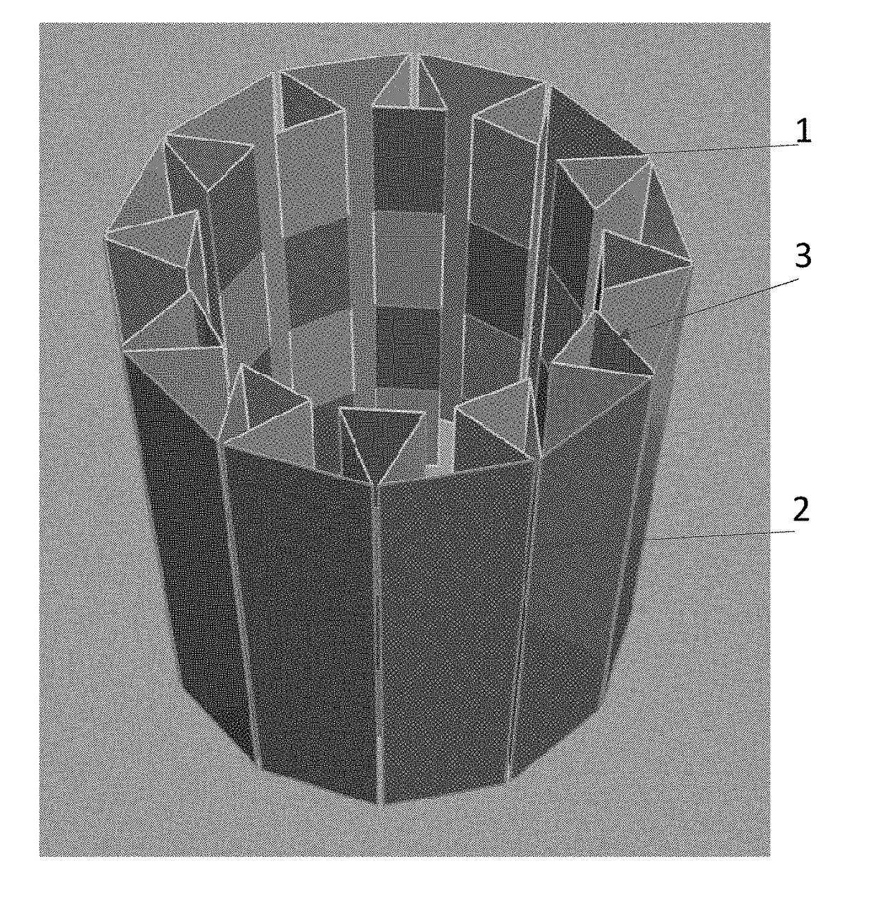
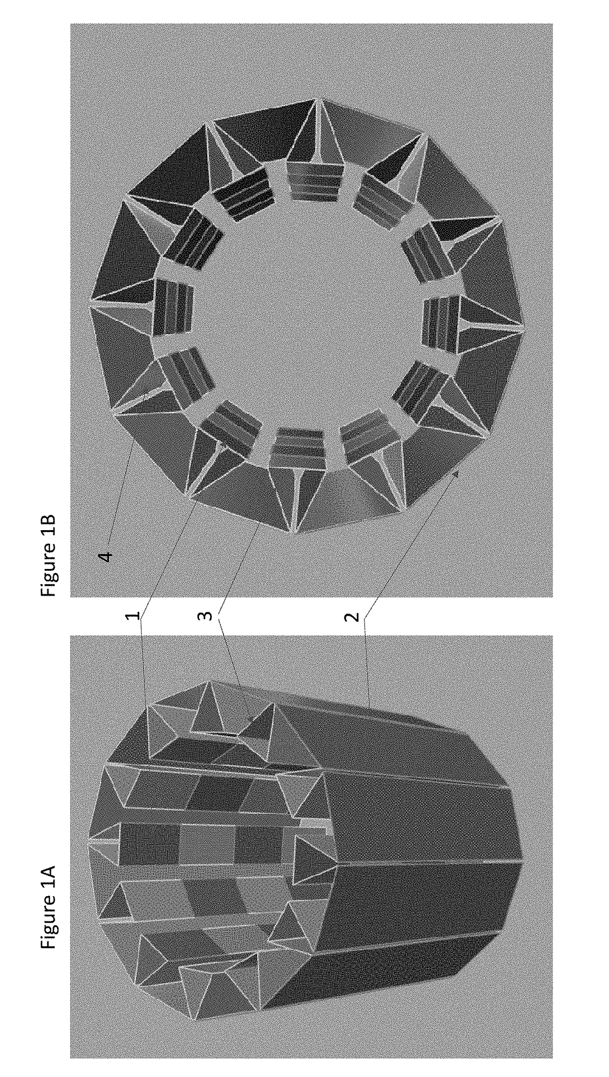
[0045]FIG. 1A illustrates one embodiment of a stretchable sensor design of the present invention. FIG. 1B illustrates a top view of the sensor in FIG. 1. The stretchable sensor design of this embodiment has 24 capacitance plates (1). On the outside of the sensor circumferentially (2) there are shielding ground plates. Between the inner layer of capacitance plates and the outer layer of ground plates, there exists an intermediate layer (3) that connects the two. This is the layer that houses the geometry sensing plates (4). Geometry sensing can be capacitance or other sensors integrated in this region.

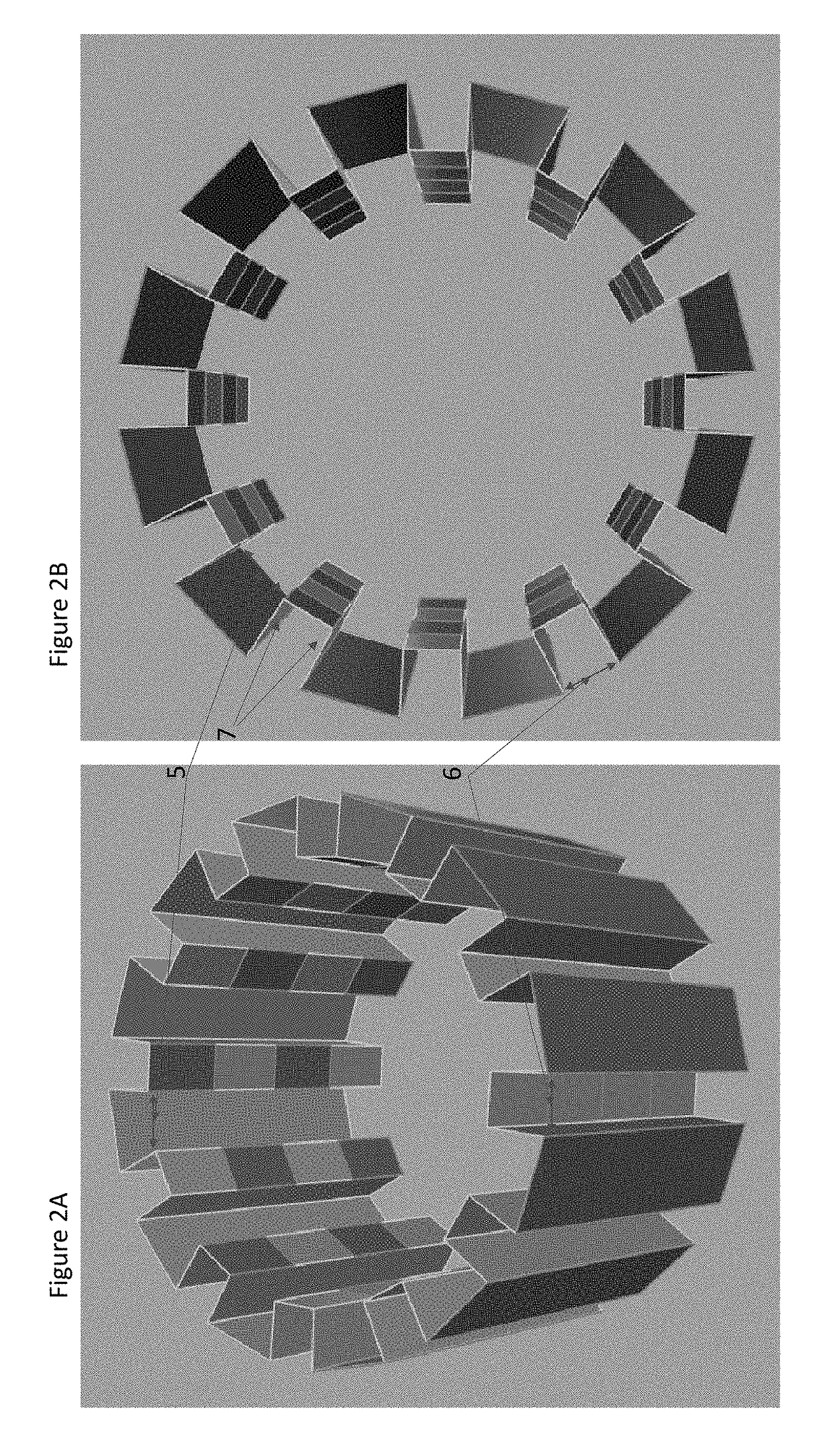
[0046]The intermediate layer can be configured in any length to allow the sensor to accommodate a larger range of stretch. The longer the intermediate layer is between the inner layer and the outer layer, the greater the sensor can stretch. More plates can be incorporated using the concepts discussed herein to form virtually any number of sensor configurations. The plates themselves can...


PUM

PropertyMeasurementUnit
diametersaaaaaaaaaa
volumeaaaaaaaaaa
stretchableaaaaaaaaaa

Abstract

A stretchable capacitance sensor having multiple components for communicating signals to a data acquisition system for reconstructing an image of an area or object located in a subject being sensed, and for calculating the shape or conformity that it is in. The stretchable sensor consists of an inner layer of plates that provide the capacitance data, a middle layer of plates that provide the geometry-sensing data, and an outer layer of plates that serves as the shielding ground layer. The configuration of all three components can be variably changed to increase the capacitance data channels, increase or decrease flexibility and stretchability of the sensor, and increase the spatial resolution of the geometry sensing feature. The sensor is adapted to communicate signals to a data acquisition system for providing an image of the area or object between the capacitance plates.

Description

BACKGROUND OF THE INVENTIVE FIELD[0001]Electrical Capacitance Volume Tomography (ECVT) is a non-invasive imaging modality. Its applications span an array of industries. Most notably, ECVT is applicable to multiphase flow applications commonly employed in many industrial processes. ECVT is often the technology of choice due to its advantages of high imaging speed, scalability to different process vessels, flexibility, and safety. In ECVT, sensor plates are distributed around the circumference of the column, object or vessel under interrogation. The number of sensor plates may be increased to acquire more capacitance data. However, increasing the number of sensor plates reduces the area of each sensor plate accordingly. A limit exists on the minimum area of a sensor plate for a given column diameter, thus limiting the maximum number of plates that can be used in an ECVT sensor. This limit is dictated by the minimum signal-to-noise ratio requirement of the data acquisition system. Sinc...

Claims


Application Information

Patent Timeline
Patent Type & Authority Applications(United States)
IPC IPC(8): G01N27/22
CPCG01N27/221G01N27/226A61B5/05A61B5/053A61B5/0535A61B5/0536A61B5/6802G01F1/64G01F17/00A61B2562/0214A61B2562/046
Inventor MARASHDEH, QUSSAIALGHOTHANI, YOUSEFZUCCARELLI, CHRISTOPHER
Owner TECH4IMAGING
Learn More