Vehicle Body Mounting Structure For a Fuel Tank
a technology for fuel tanks and mounting structures, which is applied in the field of vehicle body mounting structures for fuel tanks, can solve the problems of fuel tanks made of resin that are inferior to those made of steel plates, and buckling of side walls of fuel tanks, so as to suppress the deformation of fuel tanks and suppress the increase in fuel tanks
- Summary
- Abstract
- Description
- Claims
- Application Information
AI Technical Summary
Benefits of technology
Problems solved by technology
Method used
Image

Examples
first embodiment
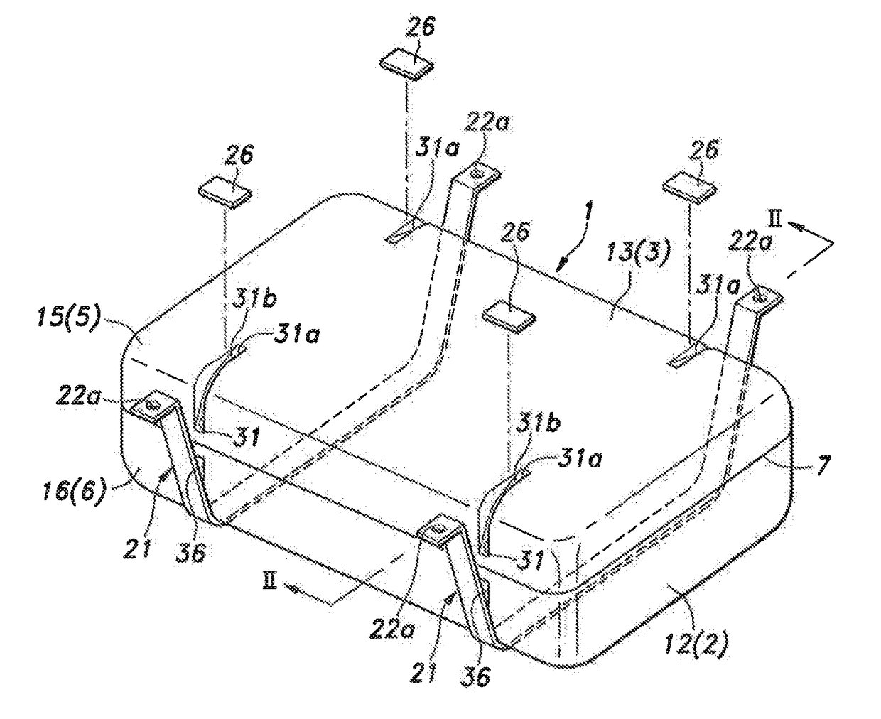
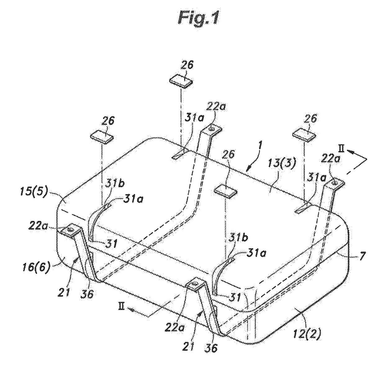
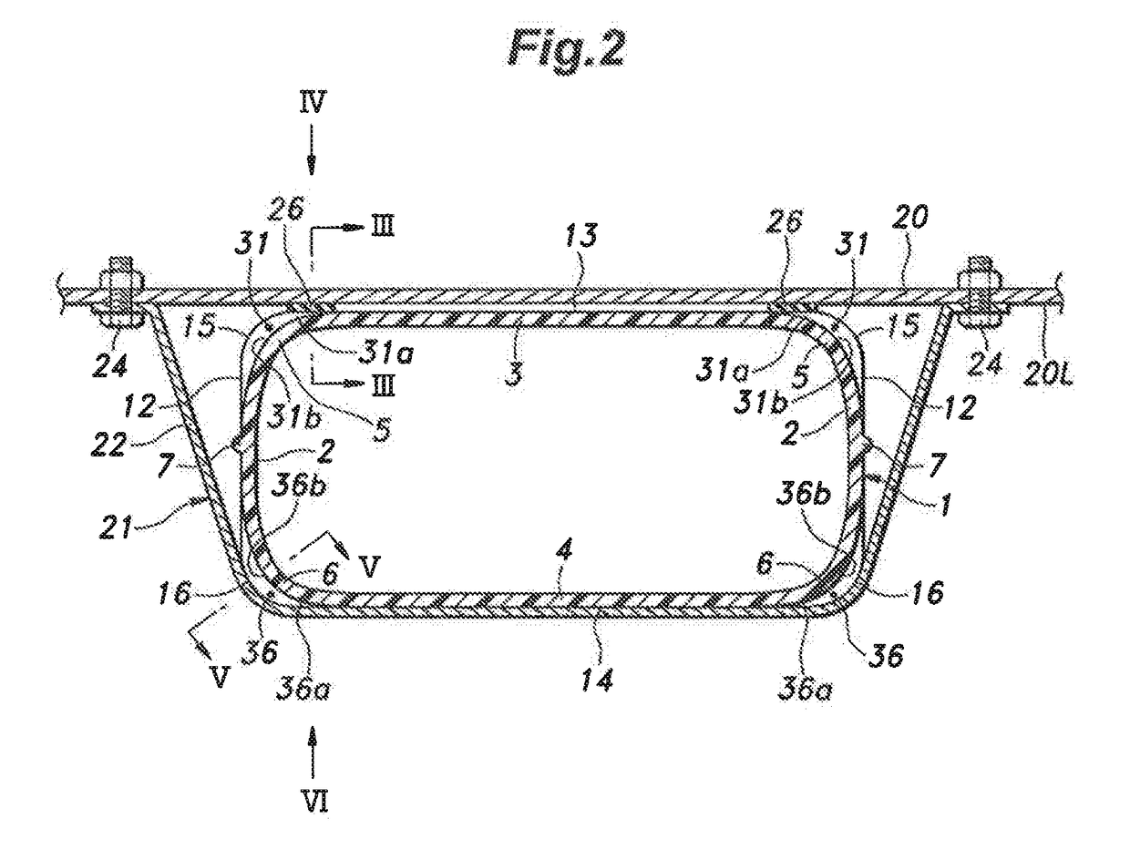
[0040]First, with reference to FIGS. 1 to 6, the first embodiment of the present invention will be described. As shown in FIGS. 1 and 2, a fuel tank 1 is a substantially rectangular parallelepiped container for storing fuel, and has an annular side wall 2, a upper wall 3, and a lower wall 4, where the side wall 2 includes a front wall, a rear wall, a right wall, and a left wall. Two walls adjoining each other and extending in intersecting directions are connected with each other. In the illustrated embodiment, the connecting part between each adjoining two walls is constituted by a curved connecting wall. Namely, the fuel tank 1 is in the shape of a rectangular parallelepiped having rounded corners. In the following description, the connecting wall that connects the upper wall 3 and the side wall 2 will be referred to as an upper connecting wall 5, and the connecting wall that connects the lower wall 4 and the side wall 2 will be referred to as a lower connecting wall 6.
[0041]It is ...
second embodiment
[0067]Next, with reference to FIG. 7, the second embodiment of the present invention will be described. The members or parts similar to those of the first embodiment will be denoted by same reference signs, and a redundant description will be omitted. This also applies to the description of the third embodiment.
[0068]As shown in FIG. 7, in this embodiment, the upper groove 31 extending downward from the upper surface 13 of the fuel tank 1 and the lower groove 36 extending upward from the lower surface 14 of the fuel tank 1 are connected with each other to form a single groove 30. Thereby, the rigidity of the side wall 2 of the fuel tank 1 is increased over its entirety in the vertical direction.
third embodiment
[0069]Lastly, with reference to FIGS. 8 and 9, the third embodiment of the present invention will be described.
[0070]As shown in FIG. 8, in the structure of this embodiment, the upper groove 31 extending downward from the upper surface 13 of the fuel tank 1 and the lower groove 36 extending upward from the lower surface 14 of the fuel tank 1 are connected with each other to form a single groove 30, in the same manner as in the second embodiment. On the other hand, the third embodiment differs from the first and second embodiments in that in the third embodiment, the upper groove 31 has a terminal end 31c in the upper surface 13 of the fuel tank 1 but does not have the upper extension groove part 31a, and the lower groove 36 has a terminal end 36c in the lower surface 14 of the fuel tank 1 but does not have the lower extension groove part 36a.
[0071]As shown in FIG. 9, the cushion member 26 is disposed such that the contact area 26A with the upper surface 13 of the fuel tank 1 surrou...
PUM
 Abstract
Description
Claims
Application Information
 - R&D
- Intellectual Property
- Life Sciences
- Materials
- Tech Scout
- Unparalleled Data Quality
- Higher Quality Content
- 60% Fewer Hallucinations
Browse by: Latest US Patents, China's latest patents, Technical Efficacy Thesaurus, Application Domain, Technology Topic, Popular Technical Reports.
© 2025 PatSnap. All rights reserved.Legal|Privacy policy|Modern Slavery Act Transparency Statement|Sitemap|About US| Contact US: help@patsnap.com