Vehicle air-conditioning unit
- Summary
- Abstract
- Description
- Claims
- Application Information
AI Technical Summary
Benefits of technology
Problems solved by technology
Method used
Image
Examples
first embodiment
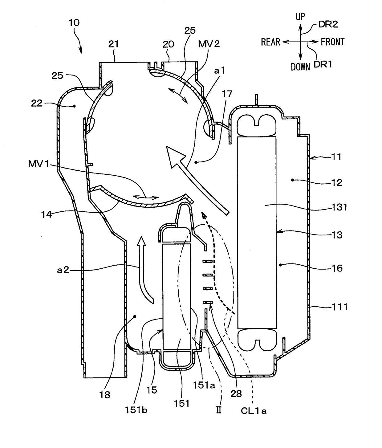
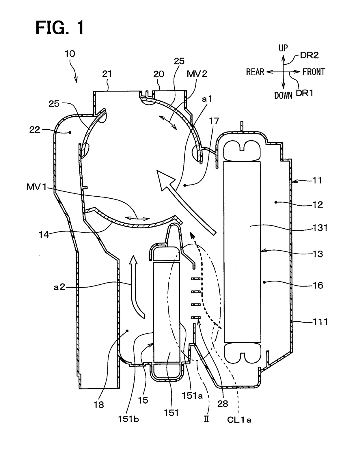
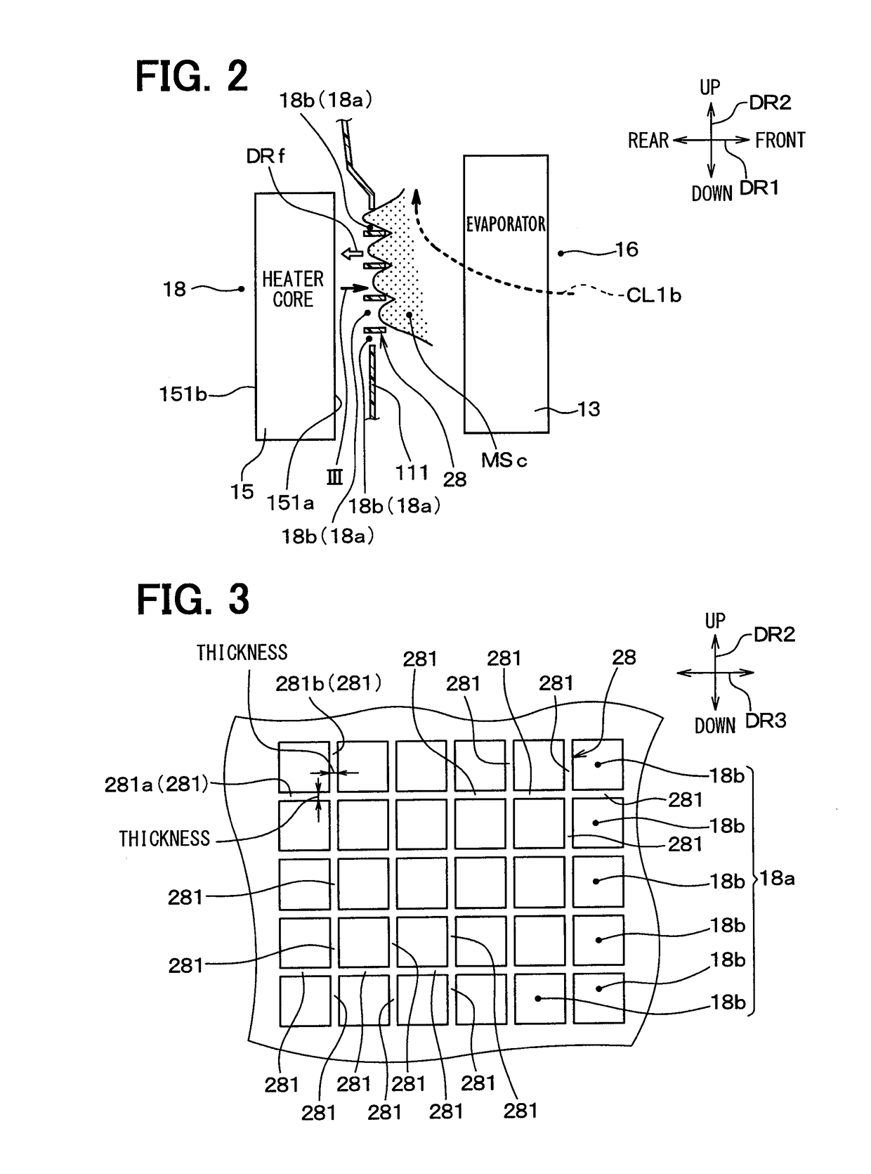
[0024]FIG. 1 is a longitudinal section illustrating a vehicle air-conditioning unit 10 (hereinafter, just referred to as air-conditioning unit 10) of an interior unit portion that is a part of a vehicle air-conditioning device having a refrigeration cycle including a compressor and a condenser provided in an engine room, for example, the vehicle air-conditioning unit 10 accommodating a heat exchanger portion. Arrows DR1, DR2 of FIG. 1 indicate directions in a vehicle mounted state where the air-conditioning unit 10 is mounted in a vehicle. A both ends arrow DR1 of FIG. 1 indicates a front-rear direction DR1 of the vehicle, and a both ends arrow DR2 indicates an up-down direction DR2 of the vehicle. A both ends arrow DR3 of FIG. 3 described below indicates a left-right direction of the vehicle, i.e. a width direction DR3 of the vehicle. The directions DR1, DR2, DR3 are perpendicular to each other.
[0025]The air-conditioning unit 10 is located at an approximately center position in the...
second embodiment
[0061]Next, a second embodiment of the present disclosure will be described. In the present embodiment, different points from the above-described first embodiment will be mainly described. Descriptions of the elements identical with or equivalent to the above-described embodiment will be omitted or simplified. This is the same as a third embodiment described below.
[0062]FIG. 6 is a longitudinal section illustrating an air-conditioning unit 10 of the present embodiment, and FIG. 6 is comparable to FIG. 1 of the first embodiment. As shown in FIG. 6, an arrangement of a heater core 15 is different from that of the first embodiment. Specifically, the heater core 15 of the first embodiment is longitudinally provide, however, the heater core 15 of the present embodiment is horizontally arranged such that an air inflow surface 151a and an air outflow surface 151b extend two-dimensionally in a horizontal direction of a vehicle.
[0063]In contrast, the hole separation portion 28 of the present...
third embodiment
[0065]Next, a third embodiment of the present disclosure will be described. In the present embodiment, different points from the above-described first embodiment will be mainly described.
[0066]FIG. 7 is a partially enlarged diagram of the present embodiment illustrating II part of FIG. 1, and FIG. 7 is comparable to FIG. 2 of the first embodiment. As shown in FIG. 7, in the present embodiment, some of multiple plate portions 281 included in the hole separation portion 28 are provided in a different way than the first embodiment.
[0067]Specifically, some of multiple plate portions 281 that are plate portions 281c, 281d positioned on both ends in an up-down direction DR2 of a vehicle are provided along a direction such that an air passing through the opening hole 18a is blown to spread from the opening hole 18a. At least some of the separation holes 18b may have an area on a downstream end larger than that on an upstream end.
[0068]In detail, an upper side plate portion 281c positioned ...
PUM
 Abstract
Description
Claims
Application Information
 - Generate Ideas
- Intellectual Property
- Life Sciences
- Materials
- Tech Scout
- Unparalleled Data Quality
- Higher Quality Content
- 60% Fewer Hallucinations
Browse by: Latest US Patents, China's latest patents, Technical Efficacy Thesaurus, Application Domain, Technology Topic, Popular Technical Reports.
© 2025 PatSnap. All rights reserved.Legal|Privacy policy|Modern Slavery Act Transparency Statement|Sitemap|About US| Contact US: help@patsnap.com


