
Real-time trajectory estimation with multi-station analysis

a multi-station, real-time technology, applied in the direction of survey, directional drilling, borehole/well accessories, etc., can solve the problems of uncertainty in the estimated trajectories, deterministic instrument errors called bias errors (or scale factor errors), and errors that may change with the working environmen

Active Publication Date: 2017-11-02
HRL LAB
View PDF8 Cites 10 Cited by
  • Summary
  • Abstract
  • Description
  • Claims
  • Application Information

AI Technical Summary

Benefits of technology

The present invention is a system for real-time trajectory estimation that works across various platforms and configurations. It uses an unconstrained optimization algorithm to deduct errors in sensor inputs and determine the position of a platform based on the optimized sensor measurements. The system can be used in vehicles, drilling wells, and other applications. It also allows for the determination of drilling attitudes and the drilling trajectory based on the optimized sensor measurements. The objective function used in the algorithm can be determined based on the sensor measurements and the theoretical values. The computer program product and computer implemented method allow for the execution of the system's operations and the performance of the associated tasks.

Problems solved by technology

These raw sensor outputs may have deterministic instrument errors called bias errors (or scale factor errors).
The errors may change with the working environments, such as the presence of local magnetic interference.
Further, these errors contribute to uncertainties in the estimated trajectories.

Method used


Image

  • Real-time trajectory estimation with multi-station analysis
  • Real-time trajectory estimation with multi-station analysis
  • Real-time trajectory estimation with multi-station analysis

Examples


Embodiment Construction

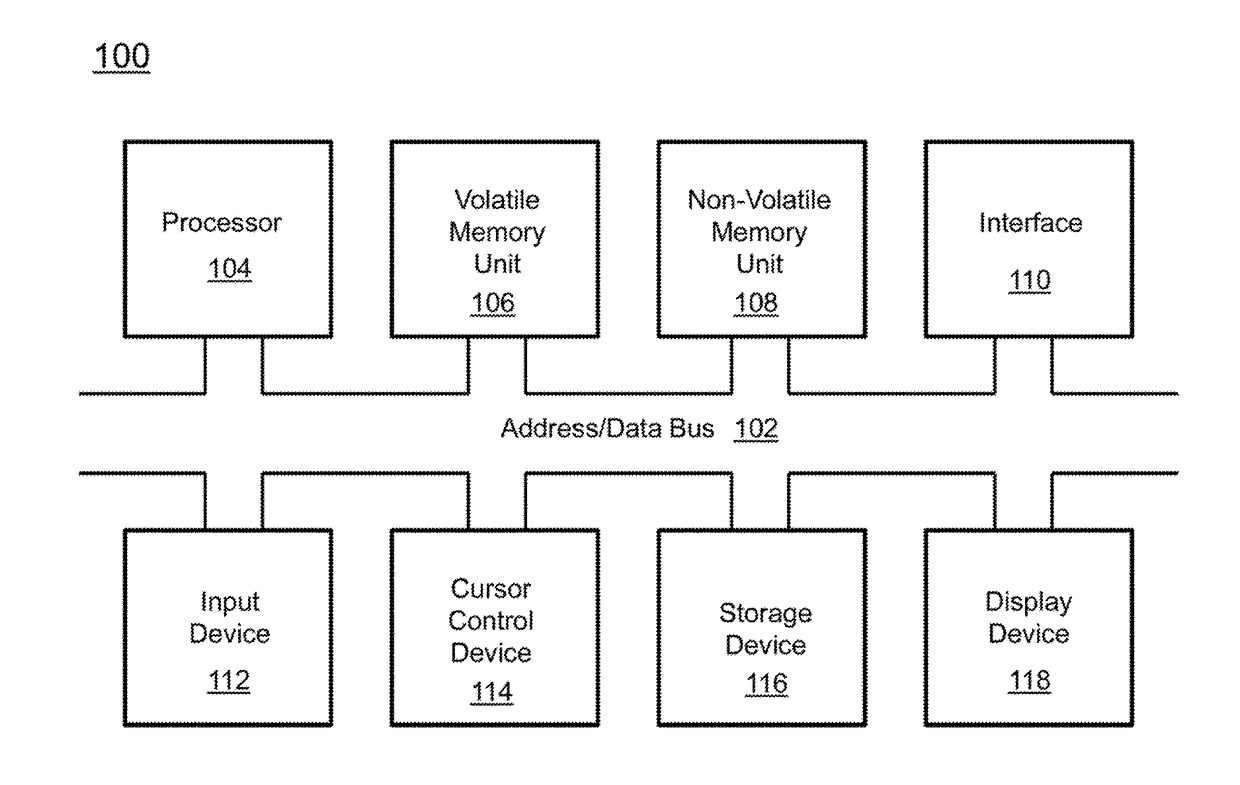
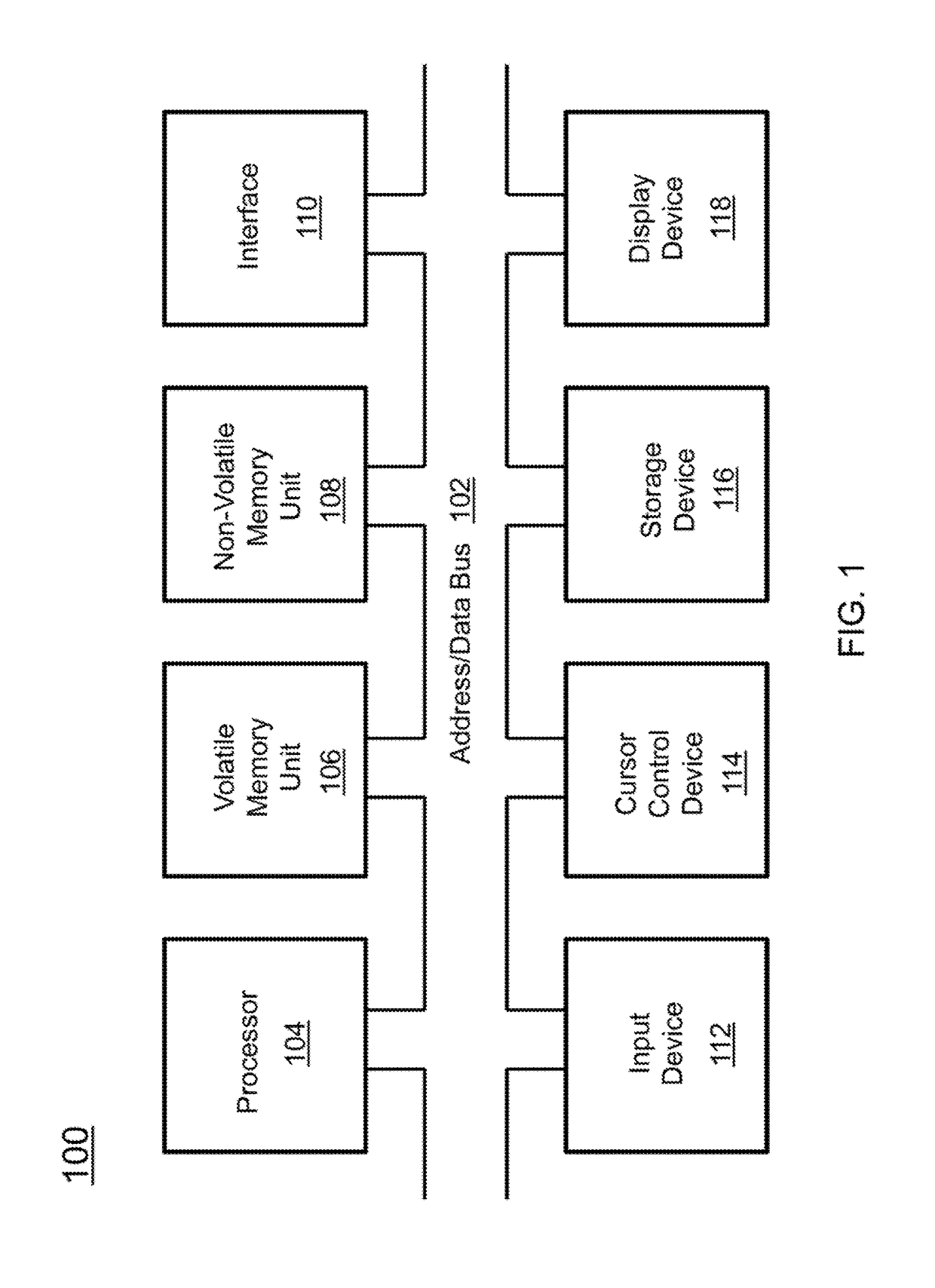
[0028]The present invention relates to a system for real-time trajectory estimation and, more particularly, to a system for real-time trajectory estimation that functions across various configurations and platforms

[0029]The following description is presented to enable one of ordinary skill in the art to make and use the invention and to incorporate it in the context of particular applications. Various modifications, as well as a variety of uses in different applications will be readily apparent to those skilled in the art, and the general principles defined herein may be applied to a wide range of aspects. Thus, the present invention is not intended to be limited to the aspects presented, but is to be accorded the widest scope consistent with the principles and novel features disclosed herein.

[0030]In the following detailed description, numerous specific details are set forth in order to provide a more thorough understanding of the present invention. However, it will be apparent to ...


PUM


Abstract

Described is a system for position estimation. A set of raw sensor outputs are acquired from a sensor of a platform. The set of raw sensor outputs are stored in non-transitory memory. A set of optimized sensor measurements is generated by deducing errors in the raw sensor outputs using an unconstrained optimization algorithm. The system determines a position of the platform based on the set of optimized sensor measurements.

Description

CROSS-REFERENCE TO RELATED APPLICATIONS[0001]This is a Non-Provisional patent application of 62 / 233,936, filed in the United States on Sep. 28, 2015, entitled, “Real Time Trajectory Estimation with Multi-Station Analysis,” the entirety of which is hereby incorporated by reference.BACKGROUND OF INVENTION(1) Field of Invention[0002]The present invention relates to a system for real-time trajectory estimation and, more particularly, to a system for real-time trajectory estimation that functions across various configurations and platforms(2) Description of Related Art[0003]Surveying of boreholes is commonly performed by drill-string-embedded sensor systems containing sets of three orthogonal accelerometers and magnetometers, and possibly gyroscopes. Ideally, these sensors provide the attitudes (i.e., position relative to a frame reference) of the drill-string at each measurement location from which the trajectory is deduced. These raw sensor outputs may have deterministic instrument err...

Claims


Application Information

Patent Timeline
IPC IPC(8): E21B47/024G01C21/16E21B7/04
CPCE21B47/024G01C21/16E21B7/04G01C21/188E21B47/022
Inventor WANG, SHUOQINSORENSON, LOGAN D.NGUYENCHANG, DAVID
Owner HRL LAB
Learn More