Controllable shock absorber for motor vehicles

a technology for shock absorbers and motor vehicles, which is applied to shock absorbers, vehicle components, springs/dampers, etc., can solve the problems of vibration dampers not providing bypass ducts in pistons, and the pressure cannot be maintained in some valve seat regions, so as to reduce the cross section, and simplify the installation process

Active Publication Date: 2017-11-02
THYSSENKRUPP BILSTEIN +1
View PDF12 Cites 2 Cited by
  • Summary
  • Abstract
  • Description
  • Claims
  • Application Information

AI Technical Summary

Benefits of technology

[0011]It is preferably provided that an opening of the single bypass duct or of the several bypass ducts is at least partially covered by a non-return disk which is formed separately from the valve disks. Instead of the valve disks, it is thus the case that a specific non-return disk serves for setting a defined bypass duct inlet cross section through which flow can pass freely. Since the non-return disk generates a cross-section reduction of the bypass duct only in one throughflow direction, the throughflow cross sections can be set separately for the two throughflow directions through selection of suitable non-return disks. Such non-return disks may be formed from plastic, and can therefore be produced very inexpensively.
[0014]It is preferable for a non-return disk for limiting the throughflow cross section of the bypass duct to be arranged coaxially and axially offset with respect to a valve disk, wherein the non-return disk and the valve disk are arranged at the same side of the piston. The non-return disk can thus be easily installed. Furthermore, through the use of such disks, the vibration damper can be easily adapted for other applications. It is however not necessary for the non-return disk to completely cover the inlet of the bypass duct; partial coverage is sufficient for a reduction of the bypass cross section.
[0016]It is preferably the case that the throughflow cross section is reduced, at least in one throughflow direction, by a non-return disk, wherein the non-return disk comprises at least one, preferably multiple, radially projecting bypass flaps. The bypass flaps partially reduce the cross section, through which flow can pass freely, of the bypass duct. By means of the geometrical design of the bypass flaps, the cross section, through which flow can pass freely, of the bypass duct can be set, and thus the pressure loss that arises as flow passes through can be adjusted. The number of bypass flaps of one / multiple non-return disk / non-return disks corresponds at least to the number of bypass duct inlet openings to be covered. As flow passes through in the respective throughflow directions, it is thus the case that pressure losses of different magnitude are set in the two throughflow directions if the bypass ducts are covered to different extents by the bypass flaps.
[0017]Here, the non-return disk is preferably designed such that the non-return disk can be mounted selectively by means of both sides on the piston such that the single bypass flap or the multiple bypass flaps reduce(s) the throughflow cross section of the bypass duct or the throughflow cross sections of the bypass ducts. This may be realized by means of the arrangement of an even number, in particular two or four, bypass flaps, wherein major parts of the bypass flaps may be arranged rotationally symmetrically with respect to one another about an axis of rotation. In this way, the installation process can be considerably simplified, because the non-return disk can be installed in any orientation. Incorrect installation can be virtually ruled out.
[0018]It is preferably provided that, on the bypass flaps, there are formed abutment surfaces for the correct orientation of the non-return disk with respect to a positioning element of the piston. In this way, installation in the correct position relative to the piston is promoted.
[0019]The invention can be used in particular in the case of vibration dampers in which each valve assembly comprises a pilot-control chamber, wherein the valve disk can be preloaded into the closed valve position by pressurization of the pilot-control chamber, wherein the pressure in the respective pilot-control chambers can be set by means of at least one pilot-control valve. In the case of such vibration dampers, by means of the claimed arrangement, a possible pressure build-up at the inlets of the bypass ducts owing to the bypassing of the vestibules does not have an effect on the pressure pattern in the vestibules. It can thus be ensured that the pressure in the vestibules is, as before, influenced primarily by the pressure in the pilot-control chambers and self-evidently the piston speed. Falsification owing to the throttling action of the bypass ducts is avoided.

Problems solved by technology

In the dynamic state, the pressure cannot be maintained in some valve seat regions owing to a relatively small inflow cross section of the associated hydraulic duct.
The vibration damper does not provide any bypass ducts in the piston.

Method used


Image

  • Controllable shock absorber for motor vehicles
  • Controllable shock absorber for motor vehicles
  • Controllable shock absorber for motor vehicles

Examples


Embodiment Construction

[0020]Further measures which refine the invention will be presented in more detail below together with the description of preferred exemplary embodiments of the invention on the basis of the figures, in which:

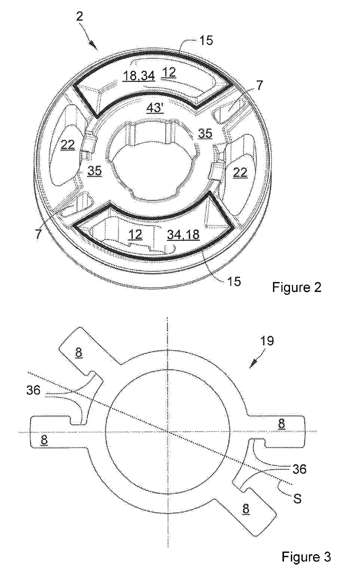
[0021]FIG. 1 shows a part of a conventional vibration damper with a valve assembly in cross section;

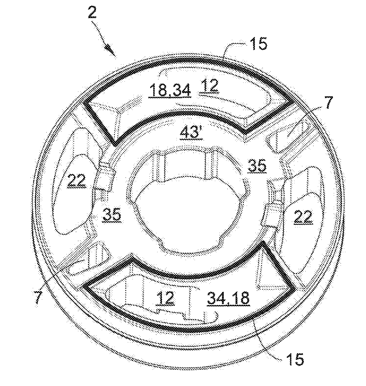
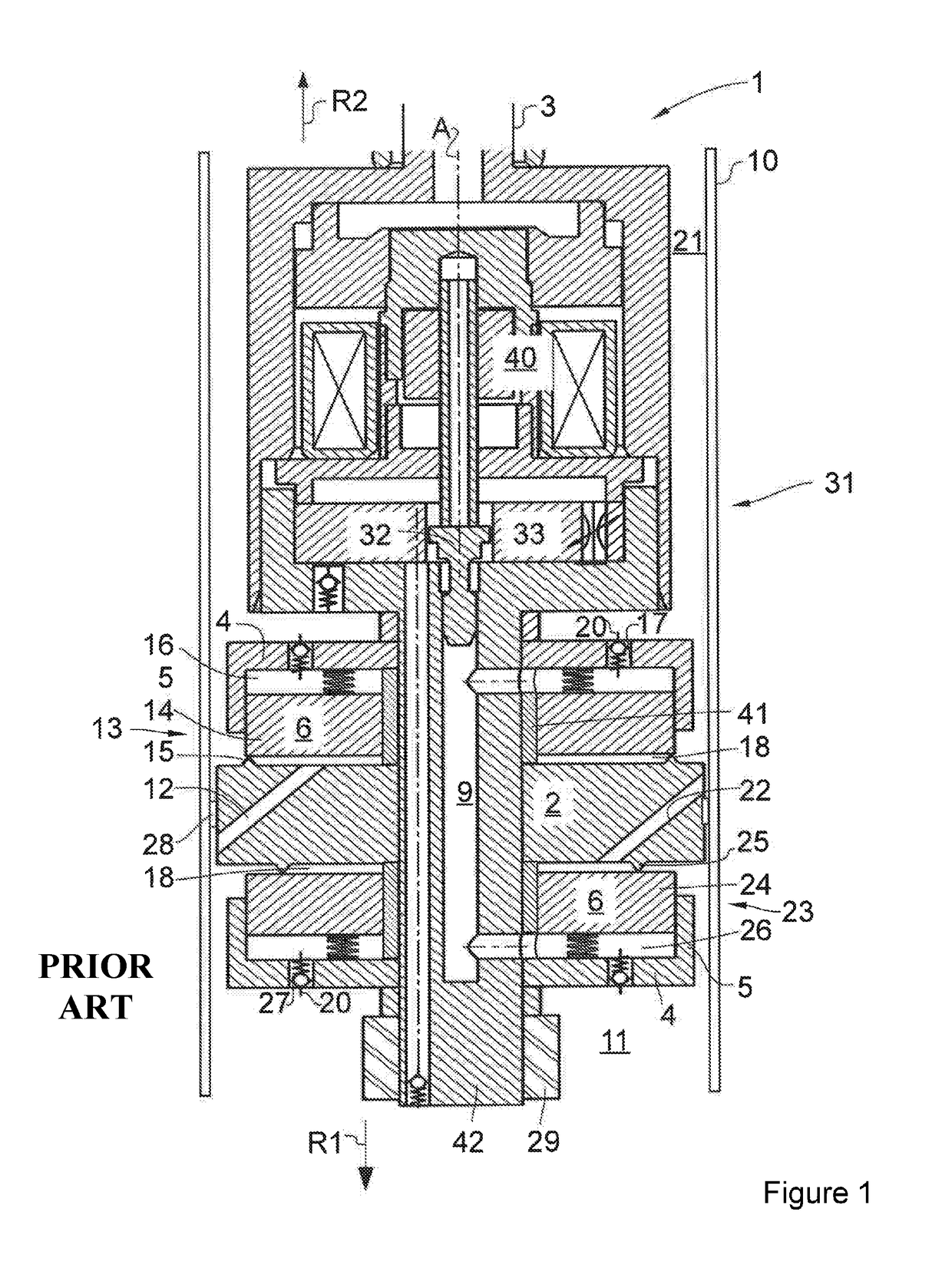
[0022]FIG. 2 shows the piston of a vibration damper according to the invention as a detail in a perspective illustration;

[0023]FIG. 3 shows the non-return disk of a vibration damper according to the invention as a detail in plan view;

[0024]FIG. 4 shows the piston as per FIG. 2 with two non-return disks as per FIG. 4 mounted thereon, in a perspective illustration;

[0025]FIG. 5 shows the arrangement as per FIG. 4 in a cross section;

[0026]FIG. 6 shows the arrangement as per FIG. 4 in a plan view;

[0027]FIG. 7 shows the piston of an alternative embodiment of the invention in cross section, with bypass flaps arranged in the bypass duct.

[0028]FIG. 1 shows the detail of a conventional vib...


PUM


Abstract

A regulable vibration damper, which may be utilized in a vehicle chassis, for example, may comprise a cylinder barrel that contains hydraulic fluid in sealed-off fashion, a piston that is axially movable within the cylinder barrel along a cylinder barrel axis and that divides the cylinder barrel into two working chambers, and a piston rod oriented parallel to the cylinder barrel axis and that is connected to the piston. The piston may comprise at least two fluid leadthroughs that connect the working chambers. A first valve assembly for damping piston movement in a first actuation direction may be arranged at a first fluid leadthrough, and a second valve assembly for damping piston movement in a second actuation direction may be arranged at a second fluid leadthrough. In the piston, one or more bypass ducts with throughflow cross sections of different size for the two throughflow directions may form fluidic connections between the two working chambers that bypass the vestibules.

Description

[0001]The present invention relates to a regulable vibration damper as per the preamble of claim 1.PRIOR ART[0002]A vibration damper of said type is known from DE 44 41 047 C1. On a piston guided axially within a cylinder barrel, there are provided pressure-dependent damping valves for an exchange of fluid between two working chambers in the rebound phase and in the compression phase. A pilot controller acts such that a controllable pressure is built up in pilot-control chambers. The pilot-control pressure forces the valve disks of the damping valves into their closed position. By means of a bypass duct system, fluid is conducted out of the working chambers into the pilot-control chambers, and thus the pressure there is increased. The pilot-control pressure is regulated by means of an externally adjustable pilot-control valve arranged in the bypass duct system. An elastic element forms the partition between the pilot-control chamber and the working chamber.[0003]A further vibration ...

Claims


Application Information

Patent Timeline
Patent Type & Authority Applications(United States)
IPC IPC(8): B62D21/11F16F9/44F16F9/348
CPCB62D21/11F16F9/446F16F9/348F16F9/3482F16F9/516
Inventor HAMERS, WOLFGANGSMELJANSKIJ, DMITRIJ
Owner THYSSENKRUPP BILSTEIN
Why Eureka
Try Eureka