
Laser cladding method and device for implementing same

a technology of cladding and laser, which is applied in the direction of lasers, coatings, instruments, etc., can solve the problems of reducing accuracy, inability to separate deposited materials and heating workpieces, and considerable loss of energy to maintain molten bath deposition, so as to achieve efficient use

Active Publication Date: 2017-11-02
CHIVEL YURY ALEXANDROVICH
View PDF5 Cites 8 Cited by
  • Summary
  • Abstract
  • Description
  • Claims
  • Application Information

AI Technical Summary

Benefits of technology

The patent describes a device that uses a cylindrical mirror to help make the most of laser light. This allows for the light to pass through the device multiple times, resulting in better use of the laser. The device also has a way to make the light return to the laser resonator, which can improve the overall efficiency of the device.

Problems solved by technology

The disadvantage of this method is the inability to separate the deposited material and heating the workpiece in the area of the laser focus spot.
The disadvantage of this method is the inability to separate the deposited material and the heating region of the workpiece to focus the laser spot, resulting in a considerable loss of energy to maintain the molten bath deposition and reduces accuracy.
The disadvantage of this device is the complexity, as well as the inability to separate the heating of the deposited material (wire) and the surface of the workpiece in the field of welding.
The disadvantage of this device is the inability to control parameters of the radiation acting on the surface of the workpiece and the powder stream.

Method used


Image

  • Laser cladding method and device for implementing same
  • Laser cladding method and device for implementing same
  • Laser cladding method and device for implementing same

Examples


Embodiment Construction

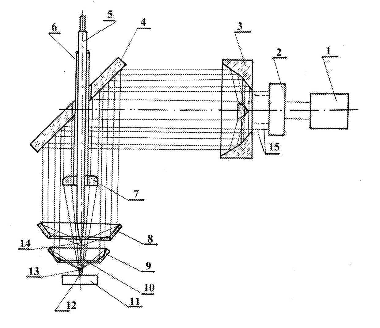
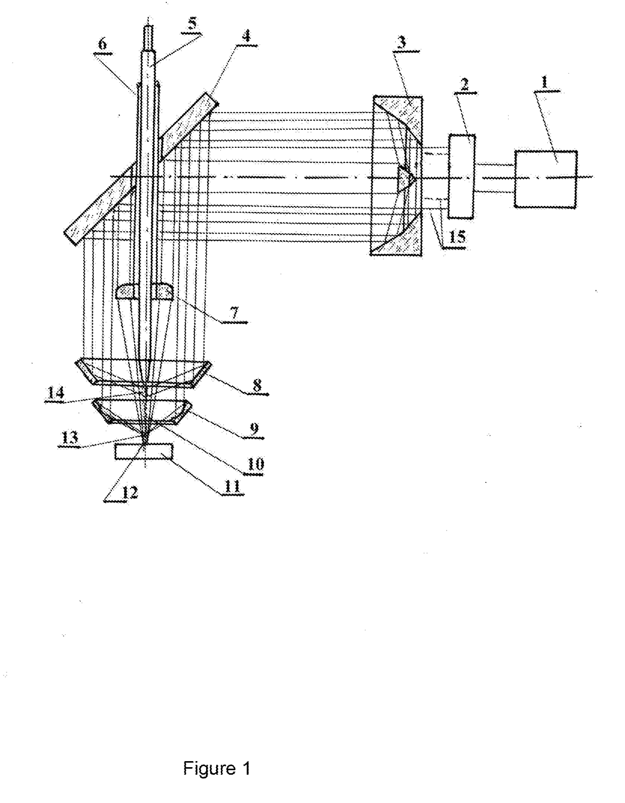
[0029]The objective of the claimed invention is to elaborate a method and apparatus for laser cladding that ensures improvement of the laser processing method, increase of productivity, reduce of energy consumption while ensuring high precision in the manufacture of parts.

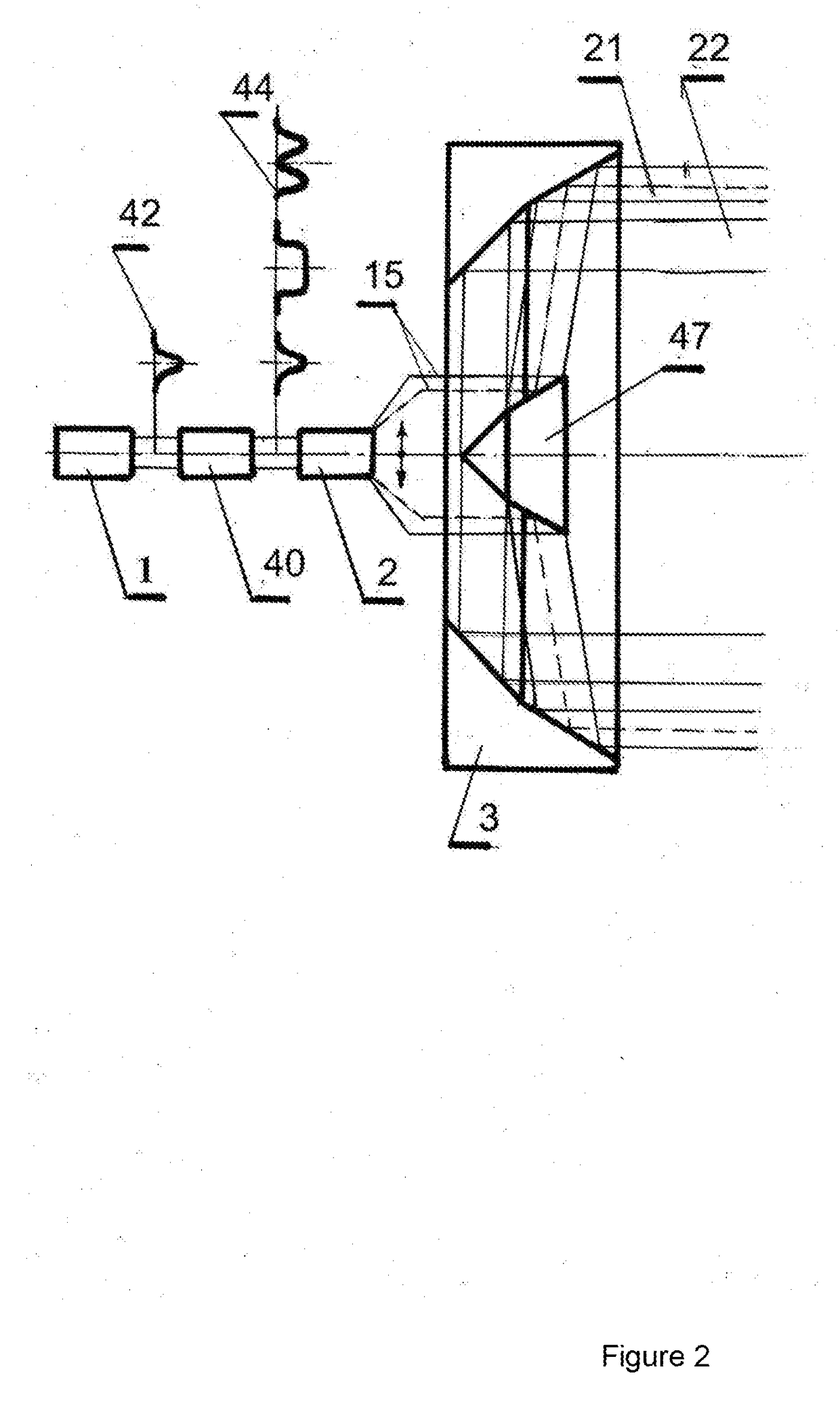
[0030]The claimed method of laser cladding consists in applying the deposited material in the focal region of the laser beam which is placed on the surface of the workpiece. Unlike other methods from the initial laser beam a series of circular annular laser beams are formed with an adjustable power distribution across the annular beams. The annular beams are transformed into a series of conical laser beams using conical lens and conical mirrors

[0031]Conical beams are separately focused as to the surface of the workpiece to heat it, and to various areas of the optical axis along which the cladding material is fed. A stream of gas, liquid, powder, heterogeneous plasma jet or wire can be used as cladding material.

[003...


PUM

PropertyMeasurementUnit
Wavelengthaaaaaaaaaa

Abstract

A method and device for laser cladding by independently heating the cladding material and the surface of the workpiece consist in formation of the series of parallel annular laser beams, possibly different wavelengths, with an adjustable distribution of laser radiation power across the annular beams. The annular beams are transformed into a series of conical beams which are separately focused along a single optical axis, along which the cladding material is fed. The device can be supplemented with a cylindrical mirror for the multipass laser radiation through the stream of cladding material with the possibility of the laser radiation return to the laser resonator.

Description

CROSS REFERENCE TO RELATED APPLICATIONS[0001]This application is a national stage application of the PCT application PCT / IB2015 / 000125 filed Feb. 6, 2015, which claims priority to Russian patent application RU 2014108831 filed Mar. 6, 2014, currently issued as a patent RU 2580180, issue date is Mar. 14, 2016.FIELD OF THE INVENTION[0002]This invention relates to laser processing of materials and can be used for laser cladding, including selective laser cladding, laser thermal processing.[0003]The objective of the claimed invention to provide a method and apparatus for laser cladding that ensures empowerment of the laser processing method, increased productivity and manufacturing precision parts, lower energy costs and high quality products.BACKGROUND OF INVENTION[0004]A method is known of laser cladding, consisting in applying weld material in the focal region of the laser beam disposed on the surface of the workpiece. The disadvantage of this method is the inability to separate the ...

Claims


Application Information

Patent Timeline
IPC IPC(8): B23K26/342B23K26/067B23K26/06B23K26/146B23K26/073B23K26/144
CPCB23K26/342B23K26/0643B23K26/0648B23K26/146B23K26/0736B23K26/144B23K26/067B23K26/064B23K26/0617B23K26/0676B23K26/14B23K26/0734B23K26/1476B23K26/34C23C4/00C23C26/02G02B5/001B22F3/115H01S3/0071B23K26/0665
Inventor CHIVEL, YURY ALEXANDROVICH
Owner CHIVEL YURY ALEXANDROVICH
Learn More