
Methods and systems for locating targets using non linear radar with a matched filter which uses exponential value of the transmit signal

a non-linear radar and transmit signal technology, applied in the field of radar, can solve the problems of difficult radar operators to distinguish them from targets of interest, large linear responses of certain clutter objects, and difficulty in detecting small targets, so as to reduce the sidelobe level of the matched filtered received signal

Active Publication Date: 2017-10-26
US SEC THE ARMY THE +1
View PDF4 Cites 28 Cited by
  • Summary
  • Abstract
  • Description
  • Claims
  • Application Information

AI Technical Summary

Benefits of technology

This patent describes a method for non-linear radar target location. The method involves transmitting a signal towards a target and receiving the signal reflected by the target. The received signal is then analyzed to determine its transform waveform, which is used as the transmit waveform in subsequent steps. A matched filter is created to filter the received signal and a recursive sidelobe minimization process is performed to reduce sidelobe levels. The technical effect of this method is improved target location accuracy.

Problems solved by technology

Unfortunately, it has been demonstrated that certain clutter objects produce large linear responses to radar probe signals.
For example, trees and rocks are capable reflecting relatively large amounts of energy, making it difficult for radar operators to distinguish them from targets of interest.
While these systems produce detailed imagery of a scene, the detection of smaller targets can still be problematic.
Modern systems that exploit Doppler phenomena face a similar problem.
In this case, large returns from stationary clutter objects can obscure slow-moving targets and, especially, if the targets reflect only a small amount of energy relative to the nearby clutter.

Method used


Image

  • Methods and systems for locating targets using non linear radar with a matched filter which uses exponential value of the transmit signal
  • Methods and systems for locating targets using non linear radar with a matched filter which uses exponential value of the transmit signal
  • Methods and systems for locating targets using non linear radar with a matched filter which uses exponential value of the transmit signal

Examples


Embodiment Construction

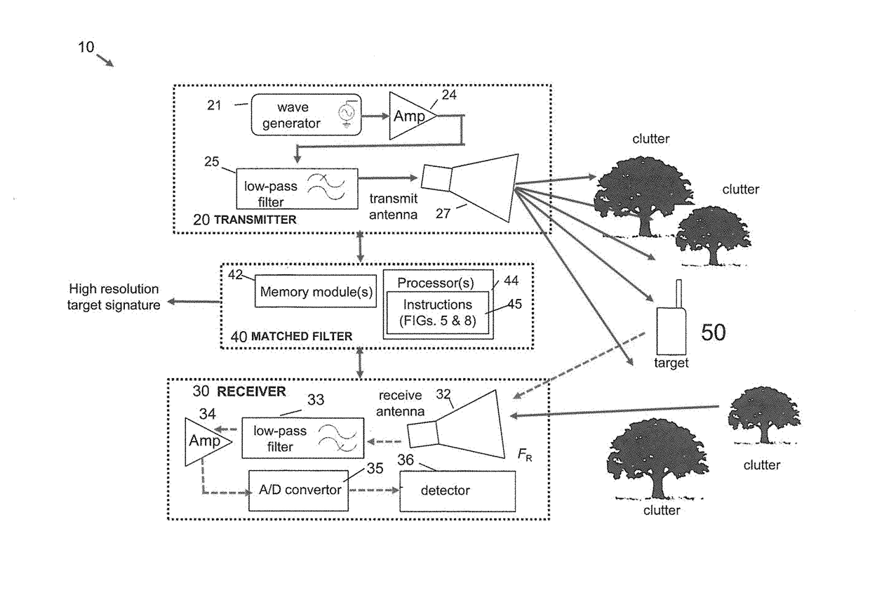
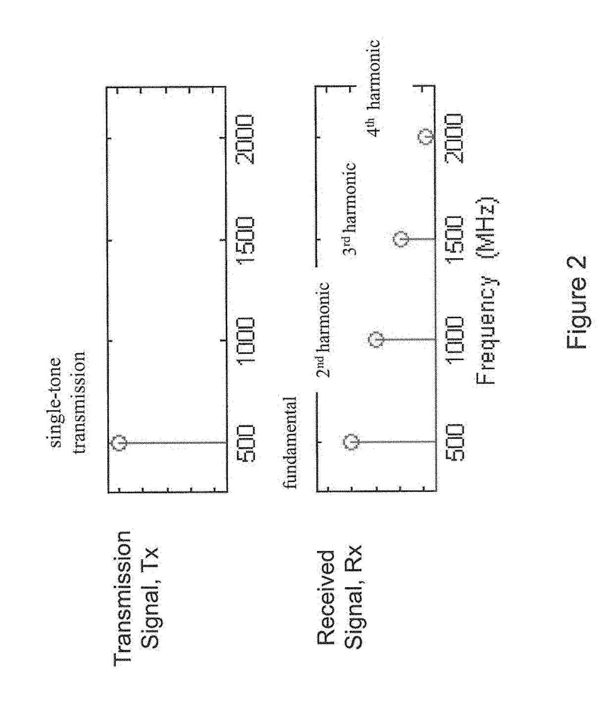
[0029]Embodiments of the present invention provide improved non-linear detection and ranging capabilities. It has been demonstrated that certain objects produce non-linear responses to radar probe signals. Nonlinear radar produces frequencies in a nonlinear target (e.g., electronics or metal object) response that are different from those transmitted by the radar, thereby separating natural clutter from the nonlinear target response. In particular, echoes can be observed at one or more harmonics of the transmitted frequencies. Thus, the processing described herein does not focus on the entire transmit waveform, which contains multiple discrete signal tones, but instead it focuses on its harmonic(s)-of-interest.

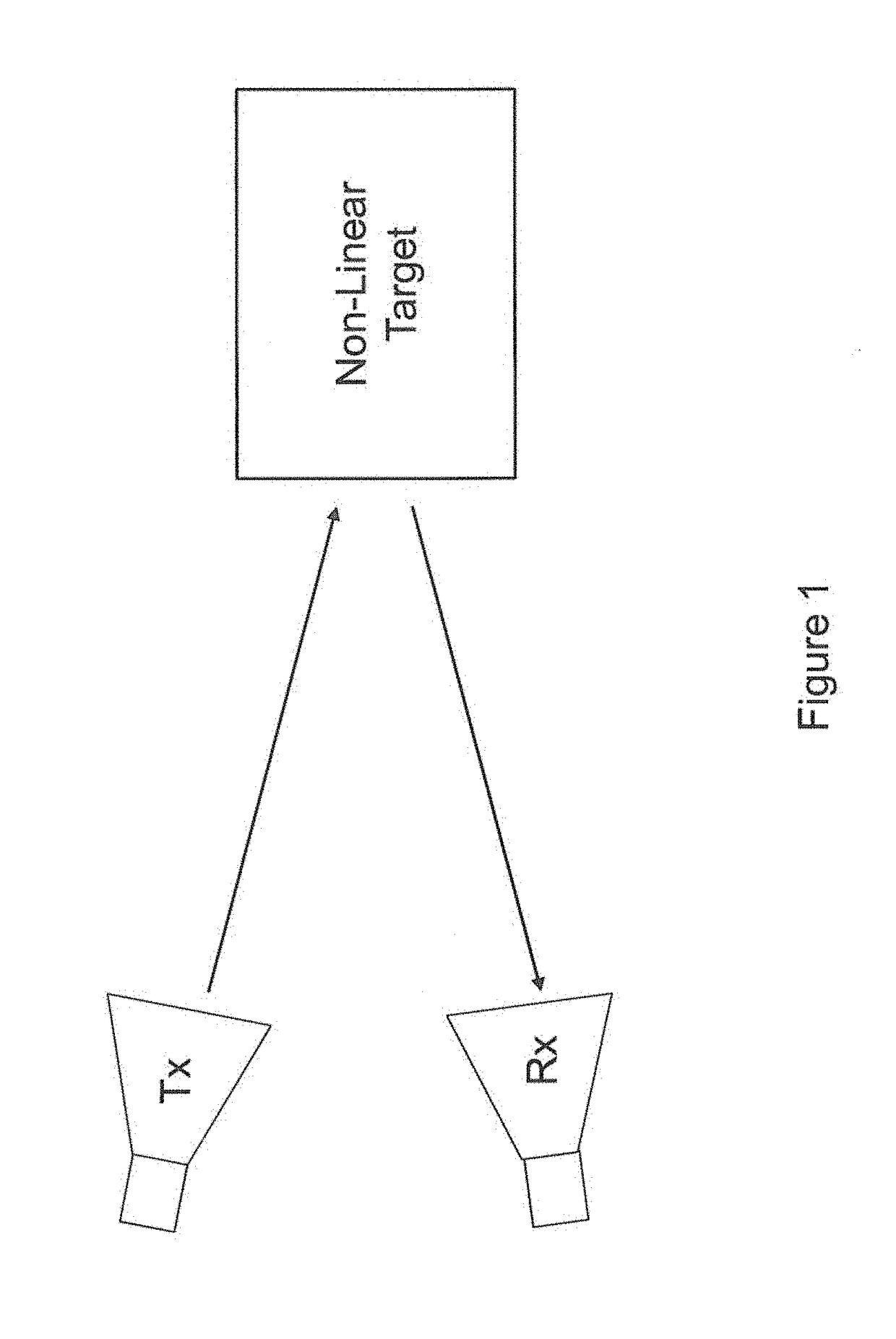
[0030]The novel methodology detects and processes harmonic target responses to a transmitted radar waveform, and in this way, it is able to localize the target in range. FIG. 1 shows a simple schematic of a non-linear radar scenario. A radar transmitter Tx emits a radar signal ...


PUM


Abstract

Embodiments of the present invention concern locating targets using non-linear radar with a matched filter which uses exponential value of the transmit signal. According to embodiments, a method of non-linear radar target location includes: transmitting a signal of a transmit waveform towards a target; receiving a signal from the target; creating a matched filter by generating an exponential function of the transmit waveform corresponding to a particular harmonic of the interest; and applying the matched filter to the received signal to generate and output a signature waveform for the target of the particular harmonic of interest. In other embodiments, the matched filtering may be combined with sidelobe reduction.

Description

GOVERNMENT INTEREST[0001]Governmental Interest—The invention described herein may be manufactured, used and licensed by or for the U.S. Government.REFERENCE TO COMPUTER PROGRAM LISTING APPENDIX[0002]A computer program listing appendix has been submitted via EFS-Web labeled as “codeappendix.” The material contained in the appendix is incorporated by reference herein as though rewritten fully herein.BACKGROUND OF THE INVENTIONi) Field of Invention[0003]This application generally relates to radar, and more particularly, to non-linear radar and processing steps, which exploit non-linear target responses.ii) Description of Related Art[0004]Historically, radar systems have operated on signals that are assumed to be echoes produced by linear systems. In linear radar systems, a pulse transmitted at one frequency will reflect off an object and produce a receive signal at the same frequency. This paradigm generally functions well, enabling radar systems to detect targets provided that their s...

Claims


Application Information

Patent Timeline
Patent Type & Authority Applications(United States)
IPC IPC(8): G01S7/292G01S7/41
CPCG01S7/414G01S7/292G01S7/354G01S13/0209G01S13/32
Inventor MAZZARO, GREGORY J.GALLAGHER, KYLE A.RANNEY, KENNETH I.MARTONE, ANTHONY F.
Owner US SEC THE ARMY THE
Learn More