
Electromagnetic release door closer

a technology of electronic release and door closer, which is applied in the field of door closers, can solve the problems of poor flexibility, and achieve the effects of convenient use, wide adjustment range, and more use requirements

Active Publication Date: 2017-10-26
OUBAO SECURITY TECH
View PDF5 Cites 9 Cited by
  • Summary
  • Abstract
  • Description
  • Claims
  • Application Information

AI Technical Summary

Benefits of technology

The present invention provides an electromagnetic release door closer that allows a door leaf to move freely between a maximum opening position and a position limited by a limiting latch bolt. The closer includes a slide rail with a slide groove and a slide cavity, a through slot between the slide groove and the slide cavity, and an electromagnetic limiting mechanism that can be fixed at any position in the slide cavity. Additionally, when the door leaf receives great impact force, the slider will drive the limiting latch bolt to compress the first spring, preventing damage to the closer device. The power-off state of the electromagnet results in the door leaf being opened or closed freely, while the strength of the second spring ensures the slider passes through the limiting latch bolt and compresses the second spring. The technical effects of this invention include wider range of adjustment and increased convenience and reliability for use.

Problems solved by technology

Under the normal use state of such a normally opened fireproof door, both the opening angle and position of a door leaf cannot be adjusted, the opening degree of the door cannot be adjusted at any time according to environmental change or use requirements, so the flexibility is poor.

Method used


Image

  • Electromagnetic release door closer
  • Electromagnetic release door closer
  • Electromagnetic release door closer

Examples


Embodiment Construction

[0019]In order to make the objective, technical solution and advantages of the present invention clearer, the present invention is further described in detail below in reference to drawings and embodiments. It should be understood that the specific embodiment described herein is only used to explain the present invention rather than to limit the present invention.

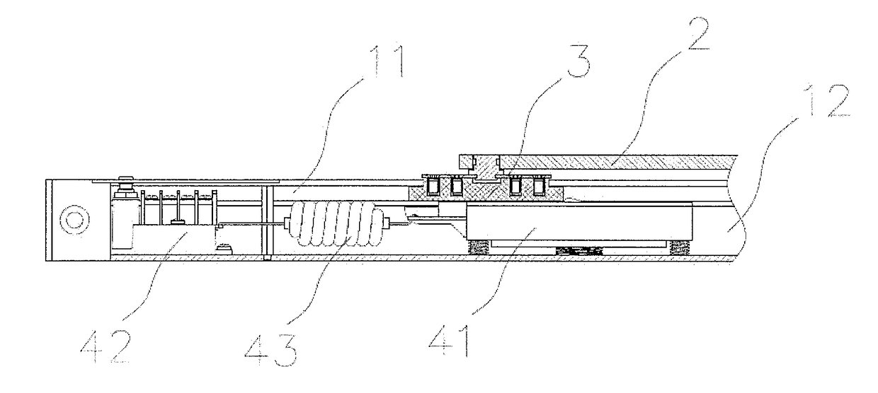
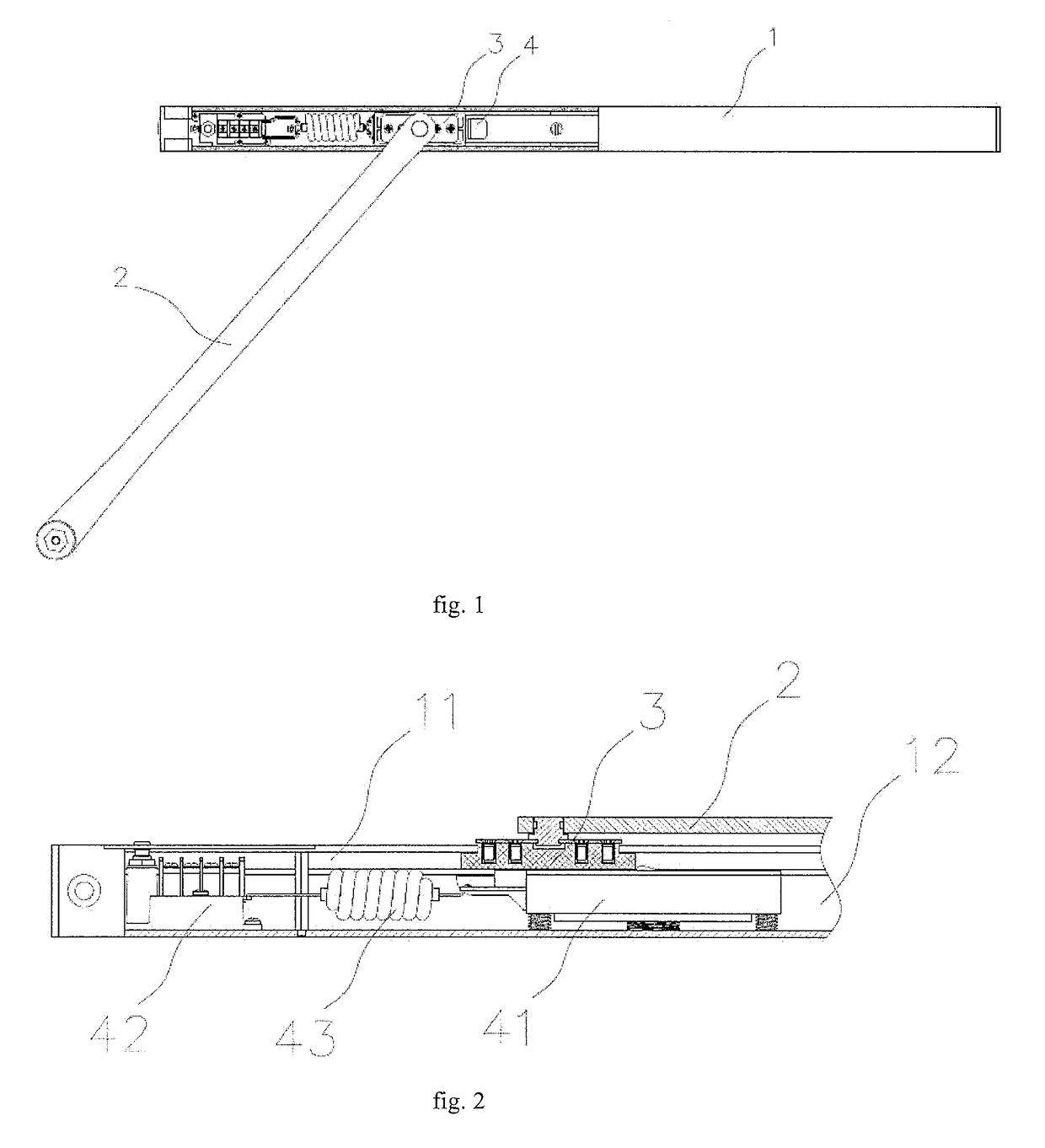
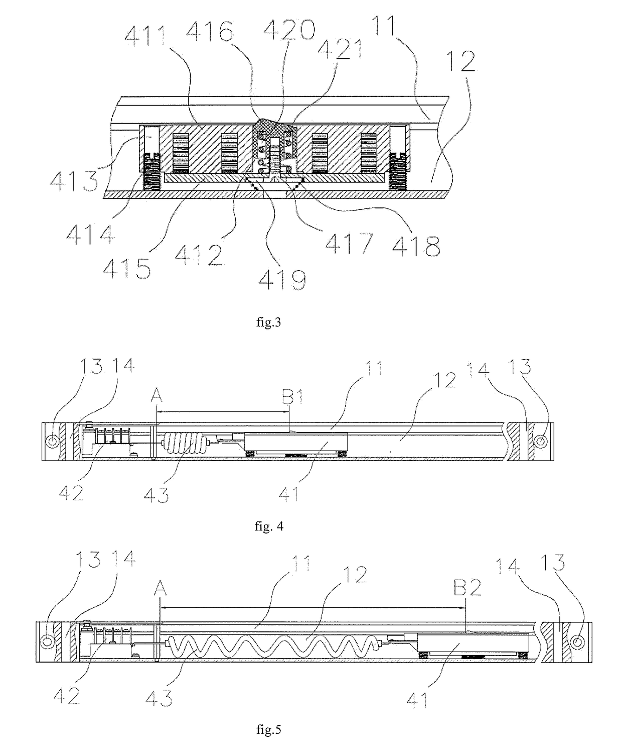
[0020]As shown in FIGS. 1-3 and FIG. 9, an electromagnetic release door closer of the present embodiment comprises a door closer body 5, a slide rail 1, and a rocker arm 2. The upper surface of the slide rail 1 is provided with a slide groove 11, the interior of the slide rail 1 is provided with a slide cavity 12 which is parallel to the slide groove 11, wherein a through slot (not shown in the drawings) which is parallel to the slide groove 11 is arranged between the slide groove 11 and the slide cavity 12, and the width of the through slot is less than the widths of the slide grooves 11 and the slide cavity 12.

[0021]One e...


PUM


Abstract

The present invention relates to the technical field of door closers, and particularly discloses an electromagnetic release door closer. The electromagnetic release door closer comprises a door closer body, a slide rail, and a rocker arm, one end of the rocker arm is articulated with the door closer body, wherein the slide rail is provided with a slide groove and a slide cavity which are parallel to each other, a through slot which is parallel to the slide groove is arranged between the slide groove and the slide cavity, wherein an electromagnetic limiting mechanism can be fixed at any position in the slide cavity. In the electrified state of an electromagnet, an electromagnetic attracting plate and the electromagnet are in a fixed state under the action of magnetic force, a limiting latch bolt is located in the slide groove, and is used to limit the sliding of a slider in the slide groove, and under this state, the slider can slide freely between the limiting latch bolt and one end of the slide groove, that is, a door leaf can move freely between a position limited by the limiting latch bolt and a maximum opening position. The defect that a door leaf can only be fixed in one specific state in the prior art is overcome, the range of adjustment is wider, and the electromagnetic release door closer is more convenient to use, and can meet more use requirements.

Description

FIELD OF THE INVENTION[0001]The present invention relates to the technical field of door closers, and in particular to an electromagnetic release door closer.BACKGROUND OF THE INVENTION[0002]Door closers are mainly applied to fireproof doors in commercial and public buildings. Besides having the function of ordinary doors, fireproof doors also have the function of preventing the spread of fire and smoke, and can prevent the spread of fire within a certain period of time, ensuring that people canevacuate. Fireproof doors usually include a normally closed fireproof door and a normally opened fireproof door, wherein the normally opened fireproof door normally keeps an opened state, so that people can pass through conveniently and ventilation and daylighting are convenient, the normally opened fireproof door can close automatically under a fire situation, playing the role of blocking smoke and fire, consequently, the problems of inconvenience brought to the passage of people by that the...

Claims


Application Information

Patent Timeline
Patent Type & Authority Applications(United States)
IPC IPC(8): E05C17/56E05F15/63E05C17/20
CPCE05C17/56E05F2015/631E05F15/63E05C17/206E05Y2600/632E05Y2201/624E05Y2201/708E05Y2201/684E05F1/105E05Y2201/462E05F15/60E05F15/00
Inventor LI, HAOJIEJIANG, GUOWEILIAO, QIAOJIEYE, LIJUN
Owner OUBAO SECURITY TECH
Learn More