
Method for purifying biogas through membranes at negative temperatures

a technology of biogas and membranes, applied in biochemistry apparatus, gaseous fuels, biochemistry apparatus and processes, etc., can solve the problems of reducing the heating value, increasing the compression and transport cost, and limiting the economic advantages of upgrading

Inactive Publication Date: 2017-10-26
LAIR LIQUIDE SA POUR LETUDE & LEXPLOITATION DES PROCEDES GEORGES CLAUDE
View PDF4 Cites 11 Cited by
  • Summary
  • Abstract
  • Description
  • Claims
  • Application Information

AI Technical Summary

Benefits of technology

The patent text is describing a device called an exchanger that can cool down gas to a very low temperature. The device can achieve a minimum temperature of -20°C to -45°C. This invention is useful for industrial applications where it is necessary to quickly cool down gas to a specific temperature.

Problems solved by technology

It may, after slight treatment, be upgraded in the vicinity of the production site in order to provide heat, electricity or a mixture of both (cogeneration); the high content of carbon dioxide reduces its heating value, increases the compression and transport costs and limits the economic advantages of upgrading it to this local use.
Although this technology makes it possible to achieve high methane recovery rates, while ensuring the quality of the biomethane produced, it nevertheless has two main limits:the electricity consumption is relatively high (i.e. ≧0.25 kWh / Nm3 crude biogas), due to two parameters: the operating pressure and the degree of recycling of a portion of the permeate necessary for achieving high yields;the number of membranes may be high (for example for a 4-stage membrane treating 750 Nm3 / h of crude biogas, it is possible to use 18 modules (each module contains more than a million fibres)).
Specifically, the intrinsic performances of polymer membranes (permeance, selectivity) are limited, and the selectivity of these materials between CO2 and CH4 requires both a relatively high operating pressure, and a multi-stage purification, with a stream recycled upstream of the compressor.
Moreover, since the performances of polymer membranes are restricted by the Robeson curve, a high selectivity, chosen to limit methane losses, requires a limited productivity, which increases the number of membranes necessary for treating a given stream of biogas.
Starting from here, one problem that is faced is to provide an improved biogas purification process, this is to say that has a lower electricity consumption and that uses a smaller number of membranes compared to a process from the prior art.

Method used


Image

  • Method for purifying biogas through membranes at negative temperatures
  • Method for purifying biogas through membranes at negative temperatures

Examples


Embodiment Construction

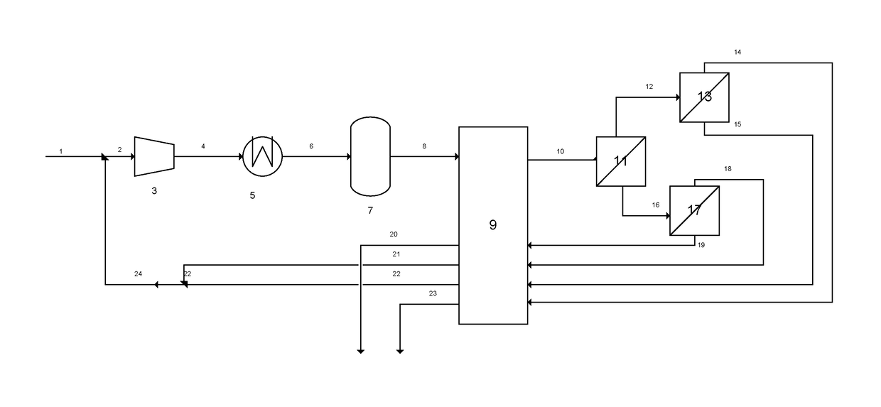
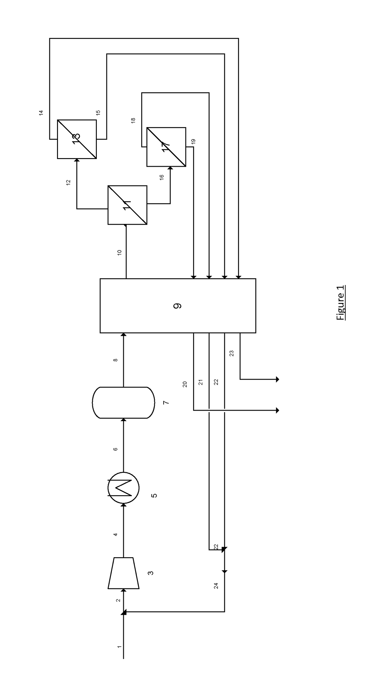
[0041]The invention will now be described in greater detail with the aid of the FIGURE which is a diagram of the plant according to invention.

[0042]The crude biogas 1, containing 43.6% CO2, 54.6% CH4, 0.8% N2 and 0.2% O2, saturated with water, at 5° C. and at a pressure of 0.1 barg, is mixed with the recycled stream 24, containing 66.6% CO2. The stream 2 is then sent to the compressor 3, where it is compressed to 9.6 barg, before being cooled to 5° C. After cooling, the water is removed in a separator, then the gas is reheated up to 15° C. The stream of gas 6 is then sent to the dryer 7. The stream 8 of dry gas, containing 51.2% CO2, then passes through the exchanger, in which it is cooled to −30° C. The stream of cooled gas enters into a first membrane state, where it is separated into two fractions. The retentate 12 is depleted in CO2 and contains no more than 30% CO2, it is sent to a second membrane stage. The permeate 16 is enriched in CO2 and contains 90% CO2, it is sent to a t...


PUM


Abstract

The invention relates to a method for membrane permeation of a gas flow including methane and carbon dioxide, wherein said gas flow is cooled to a temperature of 0° C. to −60° C. before being fed into a membrane separation unit.

Description

CROSS REFERENCE TO RELATED APPLICATIONS[0001]This application is a §371 of International PCT Application PCT / FR2015 / 052197, filed Aug. 12, 2015, which claims the benefit of FR1458225, filed Sep. 3, 2014, both of which are herein incorporated by reference in their entireties.FIELD OF THE INVENTION[0002]The present invention relates to a membrane permeation process for a gas stream containing at least methane and carbon dioxide in order to produce a methane-enriched gas stream.[0003]In particular, it relates to biogas purification, with the objective of producing biomethane in accordance with the specifications for injection into a natural gas network.BACKGROUND[0004]Biogas is the gas produced during the degradation of organic matter in the absence of oxygen (anaerobic fermentation), also referred to as methanization. This may be a natural degradation—it is thus observed in marshes or municipal waste landfill sites—but the production of biogas may also result from the methanization of...

Claims


Application Information

Patent Timeline
IPC IPC(8): B01D53/22B01D53/26F25J3/08C10L3/10B01D53/00
CPCB01D53/229C10L2290/06B01D53/227B01D53/265B01D53/26B01D53/002F25J3/08C10L3/104C10L3/106F25J2205/80F25J2220/66F25J2215/60F25J2230/30F25J2220/68F25J2270/08C10L2290/548C10L2290/08B01D53/226B01D2256/245B01D2257/504B01D2257/80B01D2258/05Y02C20/40C12M47/18Y02P20/59
Inventor BIGEARD, SARAHGARNAUD, DELPHINEHASSE, DAVID J.KULKARNI, SUDHIR S.SANDERS, EDGAR S.ZICK, GOLO
Owner LAIR LIQUIDE SA POUR LETUDE & LEXPLOITATION DES PROCEDES GEORGES CLAUDE
Learn More